10 Drive Start-Up Procedure
68 YASKAWA TOEPC7106171FD FP605 DRIVE INSTALLATION & PRIMARY OPERATION
Note:
Set H3-02, H3-10, H3-05 = 0 [Terminal A1 Function Selection, Terminal A2 Function Selection, Terminal A3 Function Selection =
Frequency Reference] to set A1 to A3 to frequency reference. The drive will add the analog input values together to make the frequency
reference.
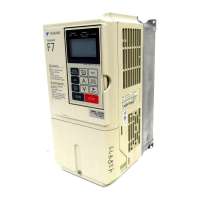
■ Set Output Signals for MFAO Terminals FM, AM
Set the signal type for terminals AM and FM to voltage or current output. Use jumper switch S5 and H4-07, H4-08
[Terminal FM Signal Level Select, Terminal AM Signal Level Select] to set the signal type.
Figure 10.10 Location of Jumper Switch S5
Terminal Types of Output Signals Jumper Switch S5
Parameter
No. Signal Level
FM
Voltage output
(Default)
H4-07
0: 0 V to 10 V
Current output 2: 4 mA to 20 mA
AM
Voltage output
(Default)
H4-08
0: 0 V to 10 V
Current output 2: 4 mA to 20 mA
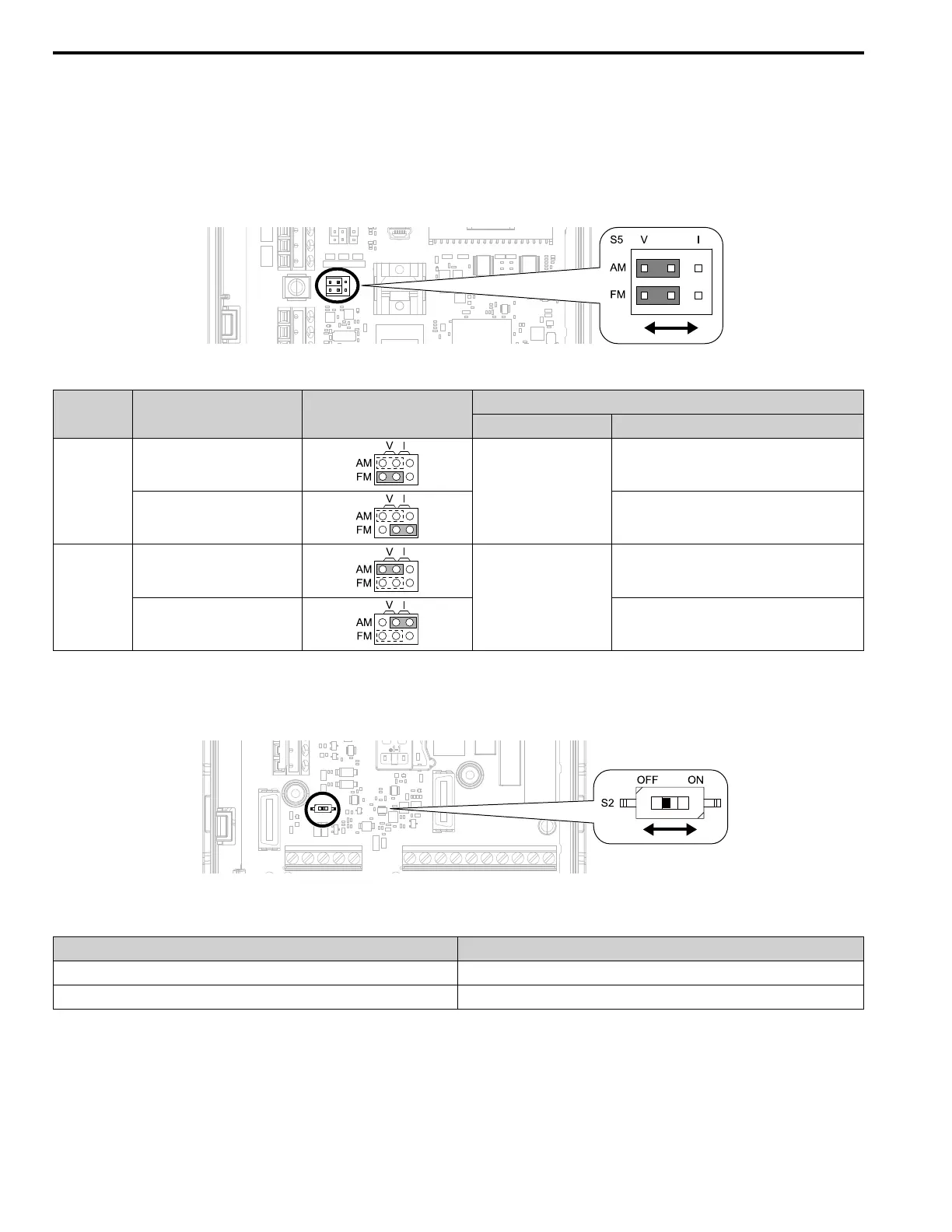
■ Switch ON Termination Resistor for MEMOBUS/Modbus Communications
When the drive is the last slave in a MEMOBUS/Modbus communications, set DIP switch S2 to the ON position.
This drive has a built-in termination resistor for the RS-485 interface.
Figure 10.11 Location of DIP Switch S2
Table 10.10 RS-485 Communications Termination Resistor Setting
DIP Switch S2 Description
ON The built-in termination resistor is ON.
OFF (Default) The built-in termination resistor is OFF.
 Loading...