Appendix 2. Installation Conditions for CENTUM V and CENTUM-XL
App.2-1
TI 33K01B10-50E
Appendix 2. Installation Conditions for
CENTUM V and CENTUM-XL
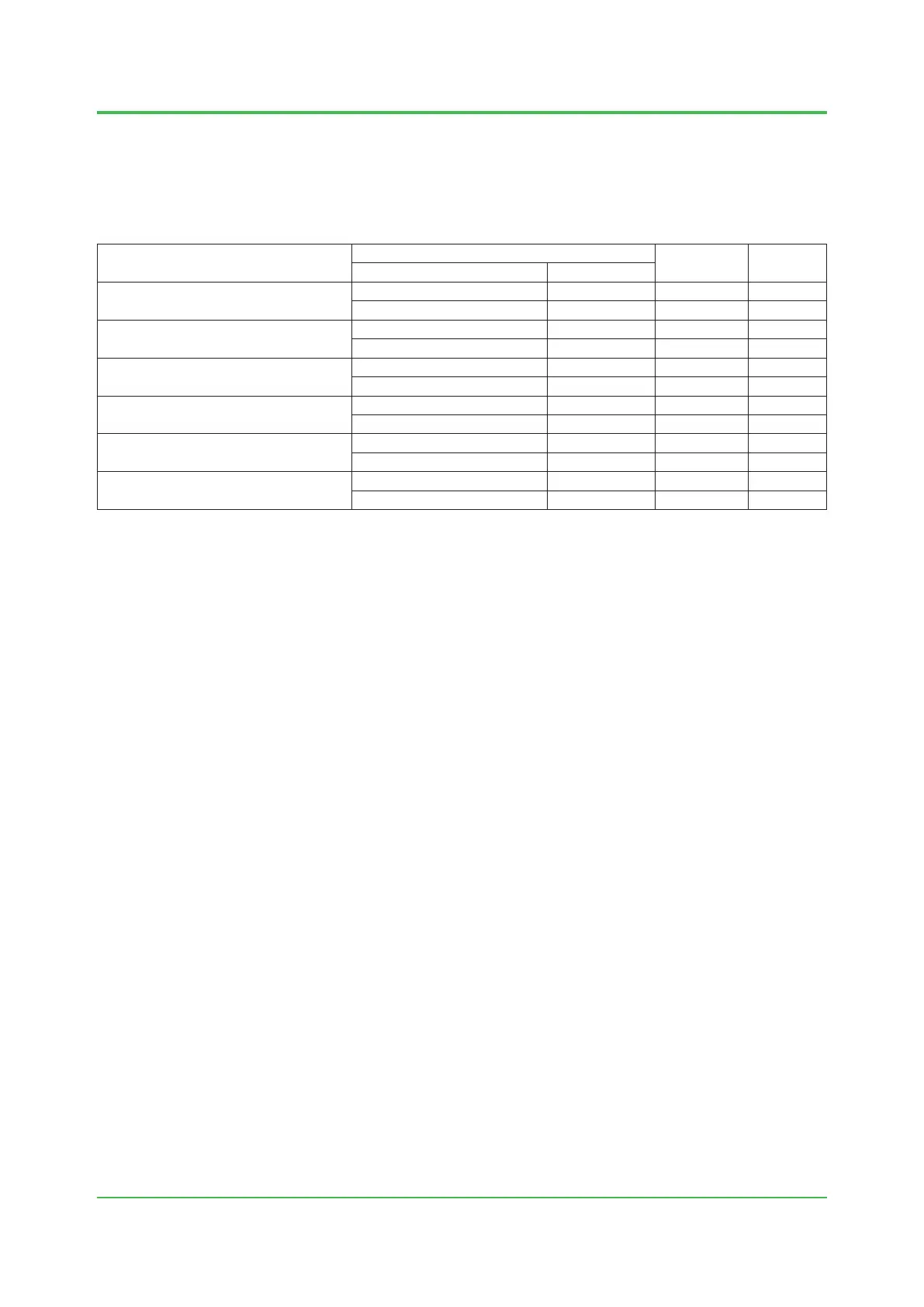
(1) Installation Conditions for CENTUM V
Equipment
Input-voltage range
Max. power
consumption
Heating
value (J/h)
Voltage (V) Frequency (Hz)
CFCS2, CFSS
Field Control Station
100/110/115/ 120 V AC±10 % 50/60±2 1300 VA 2814 x 10
3
24 V DC±10 % – 41.3 A 3402 x 10
3
CFCD2, CFSD
Duplexed Field Control Station
100/110/115/ 120 V AC±10 % 50/60±2 1570 VA 3486 x 10
3
24 V DC±10 % – 50.0 A 4158 x 10
3
CFMS2
Field Monitoring Station
100/110/115/ 120 V AC±10 % 50/60±2 470 VA 1176 x 10
3
24 V DC±10 % – 17.5 A 1428 x 10
3
CTBC2
Terminal Board Cubicle
100/110/115/ 120 V AC±10 % 50/60±2 1290 VA 2310 x 10
3
24 V DC±10 % – 27.7 A 2394 x 10
3
CGWU
Gateway Unit (Rack type mounted)
100/110/115/ 120 V AC±10 % 50/60±2 140 VA 353 x 10
3
24 V DC±10 % – 4.0 A 349 x 10
3
CFGW
Field Gateway Unit (Rack type mounted)
100/110/115/ 120 V AC±10 % 50/60±2 100 VA 353 x 10
3
24 V DC±10 % – 3.0 A 349 x 10
3
Note: The table shows the power consumption and heat dissipation when the respective components are loaded to the maximum.
Mar. 27, 2015-00
 Loading...
