54 IM 04L41B01-02E
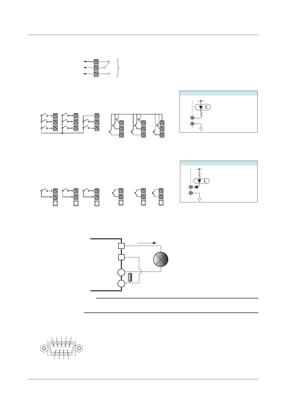
Alarm Output Terminal, FAIL Output Terminal, and Status Output Terminal (/A1, /A2,
/A3, and /F1)
C
NC
NO
Output format: Relay contact
Contact rating: 250 VAC (50/60 Hz)/3 A, 250 VDC/0.1 A (for resistor load)
Withstand voltage: 1600 VAC at 50/60 Hz for one minute
(between output terminals and the ground terminal)
Remote Control Input Terminal (/R1)
C
C
1
1~ 8
2
3
4
5
6
7
8
• Transistor input (open collector)
Internal circuit
• Relay contact input
(voltage-free contact)
C
1
2
3
4
5
6
7
8
Withstand voltage: 1000 VDC for one minute between
input terminals and the ground terminal
Input format:
Photocoupler isolation
Shared common (C)
Allowable input voltage:
5 VDC
5 V
Contact closed at 200 Ω
Contact open at 100 kΩ or greater
ON voltage: 0.5 V or less (30 mADC)
Leakage current when turned OFF:
0.25 mA or less
Pulse Input Terminal (/PM1)
H
L
H
L
H
L
H
L
H
L
H
L
H
87 6
678
L
Withstand voltage: 1000 VDC for one minute between
input terminals and the ground terminal
Input format:
Photocoupler isolation
Shared common (L)
Allowable input voltage:
30 VDC
5 V
Internal circuit
•Transistor input (open collector)
• Relay contact input
(voltage-free contact)
Contact closed at 200 Ω
Contact open at 100 kΩ or greater
ON voltage: 0.5 V or less (30 mADC)
Leakage current when turned OFF:
0.25 mA or less
24 VDC Transmitter Power Supply Output Terminal (/TPS2 and /TPS4)
Connect the DX to the transmitter as shown below.
–
+
+
–
Transmitter
Current
DX
Transmitter power
supply output
terminal
Input terminal
Shunt resistor: 250 Ω
Note
To reduce noise, use a shielded cable for wiring. Connect the shield to the functional ground
terminal or the ground terminal of the DX.
Serial Interface
Connecting to the RS-232 Connector (/C2)
2
1 3
4 5
6
7
9
8
2 RD (Received Data): Received data from the PC. Input signal to the DX.
3 SD (Send Data): Transmitted data to the PC. Output signal from the DX.
5 SG (Signal Ground): Signal ground.
7 RS (Request to Send): Handshaking signal when receiving data from the PC. Output signal
from the DX.
8 CS (Clear to Send): Handshaking signal when transmitting data to the PC. Input signal to
the DX.
* Pins 1, 4, 6, and 9 are not used.
Installation and Wiring
 Loading...