168
JOHNSON CONTROLS
FORM 201.21-NM1 (1223)
TECHNICAL DATA
CHILLER CONFIGURATION JUMPERS
There are a number of chiller conguration jumpers that
are factory wired into wire harnesses or plugs. These
jumpers typically never need to be reviewed unless in
some unlikely situation, a chiller is incorrectly cong-
ured or a loose connection occurs.
Number of Compressors
Conguration Jumper
Software packs (EPROM’s) are common between 2, 3,
and 4 compressor chillers. As a result, the VSD Logic
Board must be congured for the actual number of
compressors. The chiller is congured for the number
compressors through the use of jumpers, factory plugged
into the J1 plug on the VSD Logic Board. This hard
wiring configures the VSD Logic Board for the
number of compressors on the chiller, avoiding
mis-programming. The jumpers are only checked
at power-up. If no jumpers are sensed, or an invalid
combination is sensed and communicated to the Chiller
Control Board, start-up of the unit will be inhibited
and an “INVALID NUMBER OF COMPRESSORS
SELECTED” warning message will be displayed in the
Status display.
TABLE 1 shows the chiller number of compressors and
the associated location of the jumpers to program the
appropriate compressor conguration.
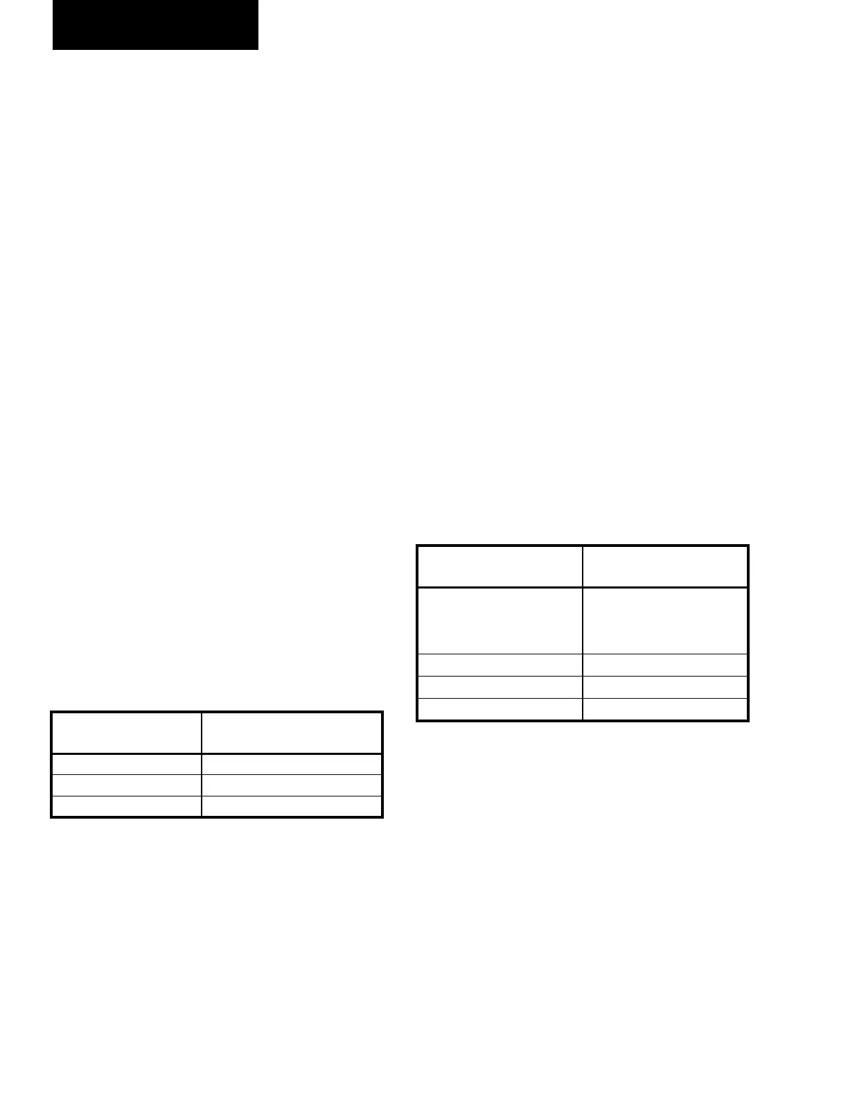
TABLE 1 - COMPRESSORS AND THE
APPROPRIATE JUMPER POSITIONS
# of
COMPRESSORS
VSD LOGIC BOARD
JUMPER POSITION
2 J1-10 to J1-9
3 J1-11 to J1-9
4 J1-12 to J1-9
VSD LOGIC TO CHILLER MICROPROCESSOR
BOARD RS-485 COMMUNICATION
CONFIGURATION JUMPERS
The Chiller Control Board and the VSD Logic
Boards communicate over an RS-485 link. The
communications link requires a matching address
to be set up at both ends. The VSD Logic Board
communications bus is congured through the use of
jumpers, factory plugged into the J5 plug on the VSD
Logic Board. The VSD Logic Board will only check
the jumper positions once at power-up.
TABLE 2 shows the VSD Logic Board Address
conguration and the associated location of the jump-
ers. The jumpers will vary according to the number
of VSD Logic Boards installed. All chillers utilize a
single VSD Logic Board and will use VSD Logic Board
Address 1.
TABLE 2 - VSD LOGIC BOARD ADDRESS JUMPER
VSD LOGIC BOARD's
ADDRESS
VSD LOGIC BOARD
JUMPER POSITION
1
J5-1 to J5-2
and
J5-3 to J5-4
2 J5-3 to J5-4
3 J5-1 to J5-2
4 NONE
 Loading...