280
JOHNSON CONTROLS
FORM 201.21-NM1 (1223)
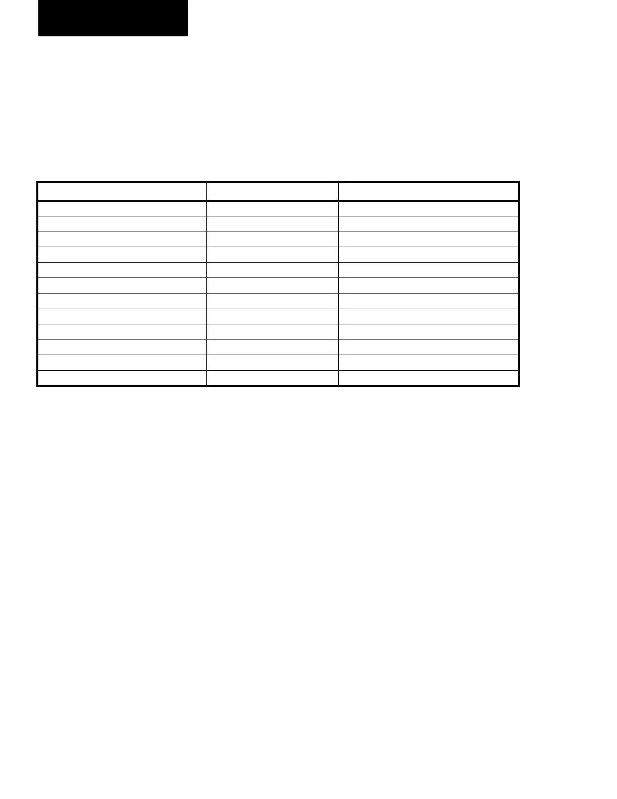
ANALOG OUTPUT CONNECTIONS
TABLE 23 lists the analog outputs and the circuit board
they are located on. The analog output signals are feed
to the associated control device from the 2 wires in the
associated plug.
TABLE 23 - ANALOG OUTPUT CONNECTIONS
BOARD HEADER ANALOG OUTPUT
Chiller Control Board J15-1 to J15-2 Sys 1 Flash Tank Feed Valve
Chiller Control Board J15-3 to J15-4 Sys 1 Flash tank Drain Valve
Chiller Control Board J15-5 to J15-6 Sys 2 ash Tank Feed Valve
Chiller Control Board J15-7 to J15-8 Sys 2 Flash Tank Drain Valve
Chiller Control Board J14-1 to J14-6 Sys 3 Flash Tank Feed Valve
Chiller Control Board J14-2 to J14-7 Sys 3 Flash Tank Drain Valve
Chiller Control Board J14-3 to J14-8 Sys 4 Flash Tank Feed Valve
Chiller Control Board J14-4 to J14-9 Sys 4 Flash Tank Feed Valve
Chiller Control Board J25-1 to J25-5 Sys 1 Condensor Fan Speed (Future)
Chiller Control Board J25-2 to J25-6 Sys 2 Condensor Fan Speed (Future)
Chiller Control Board J25-3 to J25-7 Sys 3 Condensor Fan Speed (Future)
Chiller Control Board J25-4 to J25-8 Sys 4 Condensor Fan Speed (Future)
MICRO PANEL
 Loading...