AGRICULTURAL MACHINE PTO DRIVE
A 93a A 94
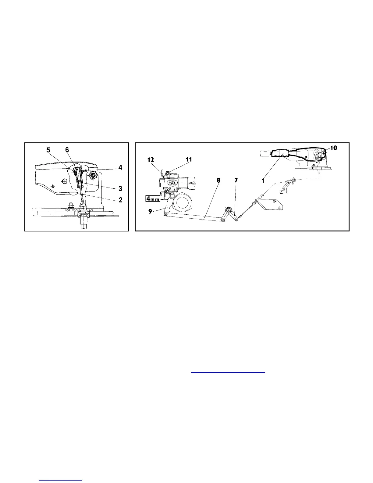
PTO CLUTCH MECHANICAL CON-
TROL
Mechanical control actuates the PTO
clutch levers through the thrust bearing.
Disengaging mechanism consists of:
1. Lever.
2. Push-pull cable.
3. Adjusting nut.
4. Adjusting screw
5. Pin
6. Push-pull cable bolt
7. Double-arm lever.
8. Pull link.
9. Shaft with lever.
10. Switch
11. Bearing
12. Disengage levers of travel clutch
ADJUSTING PROCESS
1. Remove the plastic cover of PTO
clutch hand control lever
2. Loosen the adjusting screw (4). You
will loosen the nut (3) by this way.
3. Adjust the play between bearing (11)
and clutch levers (12) by means of
adjusting nut (3) so that, to be 4 mm
play between bearing (11) and clutch
levers (12), the play must not be
lower than 2,5 mm. Hold the push-pull
cable screw (6) in adjusting nut (3) to
avoid its rotation together with ad-
justing nut (3) and so to avoid ply
apart of push-pull cable wire (2).
4. Secure the adjusting nut (3) by ad-
justing screw (4). Pay attention that
the adjusting nut (3) bears on upper
surface of pin (5).
5. Indicator light must be ´on´ after rais-
ing lever (1) into position in that the
clutch is disengaged.
6. Control force on the lever (1) is
maximally 200 N when correctly ad-
justed travel clutch disengage levers.
travel clutch disengage levers must
be adjusted if the force is excessively
increased ( approximately twice).
PDF byl vytvo’en zkuˇebns verzs FinePrint pdfFactory http://www.fineprint.cz
 Loading...