HYDRAULIC SYSTEM
A 108
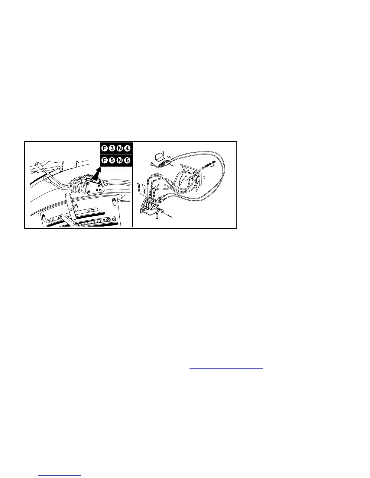
∗SELECTIVE CONTROL VALVE
2nd & 3rd selective control valve (SCV)
consists of two sections. Each section
has two pressure outlets (marked by
°3,4,5,6°). Those are alternatively noc-
nected with:
a - quick-couplers (°3,4,5,6°), located
on the rear panel
b - front three point hitch circuit for
lifting and lowering (quick-couplers
°5,6°)
c - front quick-couplers located on front
panel (quick-couplers °3,4°)
Quick-couplers °3,4° are located on the
rear panel even for alternative No °2 and
3°.
Both sections are equipped with floating
position (labeled F), sections with outlets
°5, 6° are moreover equipped with lock in
both pressure positions. The spool valve
in this section is automatically turned
into neutral position when the pressure
reaches the relieve valve pressure.
SCV control levers are located on the
right fender in the cab nearby hydraulic
control levers.
∗FRONT OUTER CIRCUIT OUTLETS
Front outer outlets are equipped with the
three quick-couplers located on panel,
quick-couplers °3,4° are alternatively
pressurised. The third quick-coupler °0°
is directly connected with the differential
housing space and is intended for the oil
coming back from outer hydraulic
implements.
PDF byl vytvo’en zkuˇebns verzs FinePrint pdfFactory http://www.fineprint.cz
 Loading...