28 “Operation and installation manual” - “Terra 360 Series 2 - CE”
EN
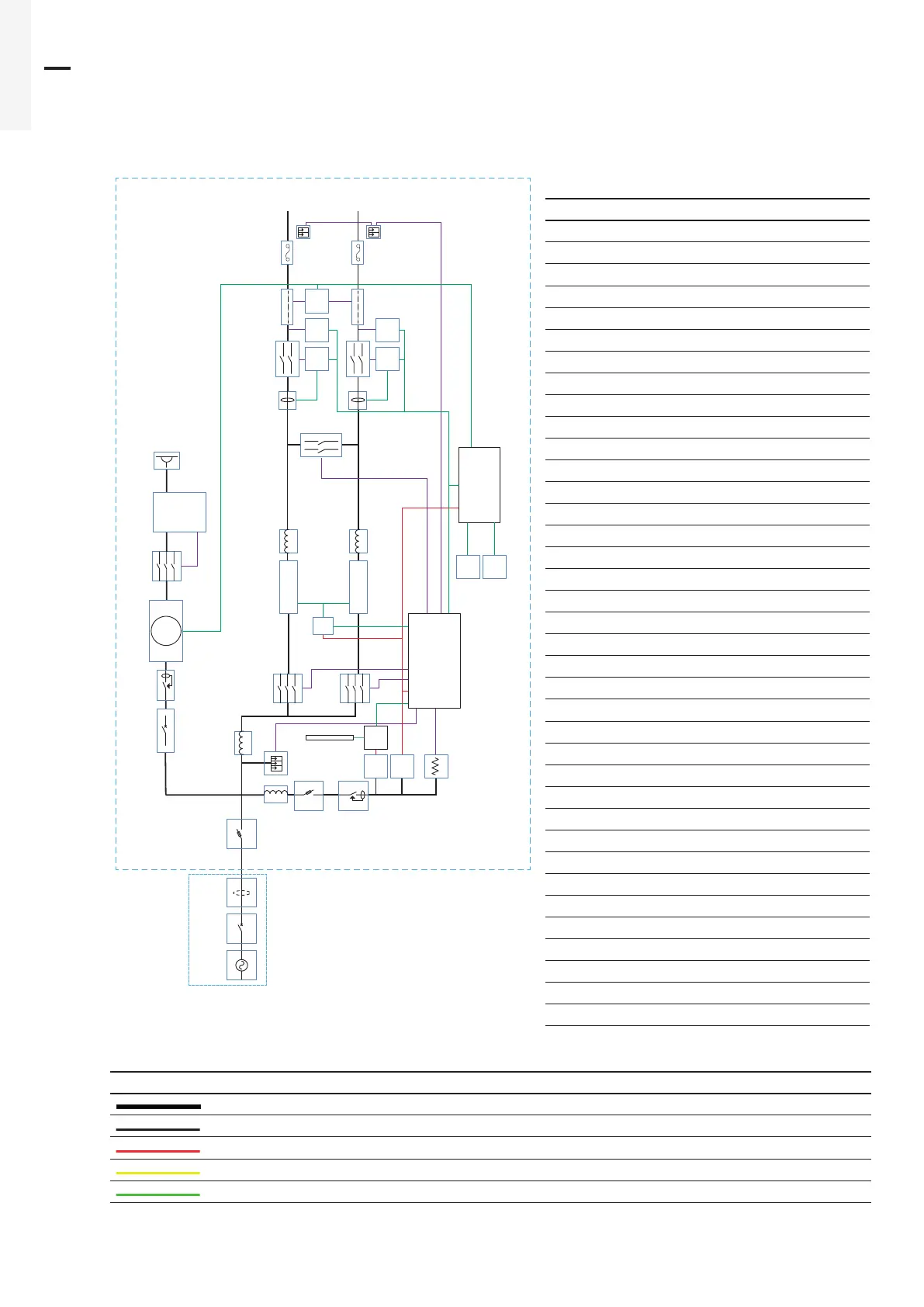
3.11 Working principles
3.11.1 Block diagram - Terra 60
Par. Description
A Fused manual switch
B Auxiliary fuse switch
B1 Magnetic circuit breaker**
B2 Auxiliary magnetic circuit breaker**
C Auxiliary residual-current device
C1 AC socket residual current device**
D AC surge-protection device
E LED strip power supply
F Auxiliary power supply
H Heater
I LED strip
J DC fuse
K Interlink contactor
L Led strip control board
N DC surge protection device
O Speaker
P AC contactor
P1 AC socket contactor
Q Power bridge
R Power module
S EMC filter
T Auxiliary transformer
U Overcurrent protection device
V DC contactor
W Shunt current
W1 AC metering**
X DC charge protocol interface
X1 AC charge protocol interface**
Y Insulation monitor interface
Z Meter reading unit
A1 Cabinet controller board
A2 Touchscreen display
S1 AC cable
U1 Charge cable
EB External distribution box
MC1 Upstream magnetic circuit breaker
LD Upstream Leakage detect
* Relevant if the EVSE has liquid cooled cables
** Relevant if the EVSE has an AC charge option
Colours Description
Bold lines: power connection
Thin lines: auxiliary power connection
Control bus
Control signal or monitoring signal
CAN bus
Q
PP
S
S
S
R
S
R
N
J
W
V
X
Y
Z
N
J
X
Y
U
W
V
U
A1
FE
OB
B2
A
B1
C1
W1
P1
S1
LD
MC1
EB
AC
C
D
L
I
H
A2
K
U1
U1
I1
X1

 Loading...