ACS 400 User’s Manual 135
Output signal source selection
It is possible to control both the relay outputs 1 and 2, as well as the analog output from serial
communication channel 1.
Relay outputs can be controlled in the following way:
Step 1: Configure the ACS 400 to supervise the value of any of the parameters 131-133 using the
parameters in group 32
SUPERVISION.
Step 2: Configure a relay output 1 or 2 to respond to the status of one of the supervised
parameters.
The selected relay can now be turned on or off by writing to supervised parameter (131-133) some
value that is either above or below the given supervision limits.
Refer to Table 16 for more information on required parameter settings. With the given settings,
writing any value 100 - 255 to parameter 131
SER LINK DATA 1 causes the relay output 1 to activate.
Writing any value 0 - 99 to parameter 131 causes the relay output 1 to deactivate.
Refer to Table 17 for information on analog output control.
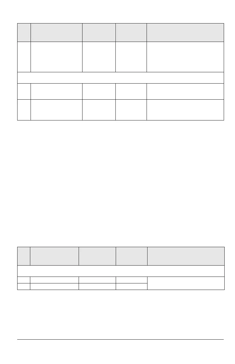
Table 16 Relay output control.
1106 EXT REF2 SELECT 0 = KEYPAD
1 = AI1
...
8 =
COMM
9 = COMM+AI1
10 =
COMM*AI1
8 (
COMM),
9 (
COMM+AI1)
or
10 (
COMM*AI1)
Fieldbus reference 2 is used when EXT2
is selected as control location. See
section References below for information
on the alternative settings.
Group 16
SYSTEM CONTROLS
1601
RUN ENABLE 0 = NOT SEL
1...5 = DI1 ... DI5
6 =
COMM
6 (COMM) The run enable signal is given through
serial communication (Control Word bit
3).
1604
FAULT RESET SEL 0 = KEYPAD ONLY
1...5 = DI1 ... DI5
6 =
START/STOP
7 = COMM
7 (COMM) Fault reset is executed through serial
communication (Control Word bit 7).
Code Parameter Name
Alternative
Settings
Setting for
Standard
Modbus
Function/Information
Group 01
OPERATING DATA
0131
SER LINK DATA 1 0 - 255 - Controlling data for the relay outputs.
0132
SER LINK DATA 20 - 255 -
Code Parameter Name
Alternative
Settings
Setting for
Standard
Modbus
Function/Information
http://nicontrols.com

 Loading...


