ACS 400 User’s Manual 11
H Floating Network
Make sure that no excessive emission is propagated to neighboring low voltage networks. In some
cases, the natural suppression in transformers and cables is sufficient. If in doubt, the supply
transformer with static screening between the primary and secondary windings can be used.
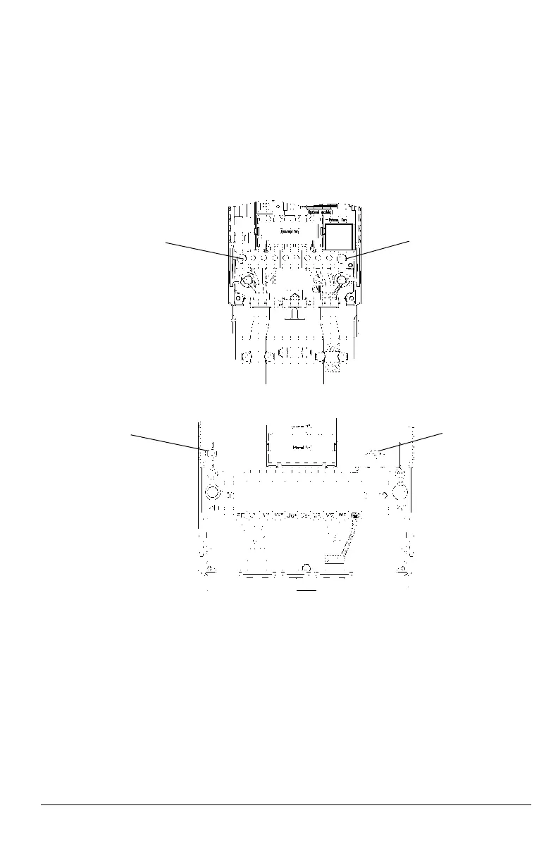
Note! Remove both grounding screws otherwise you may cause danger or damage the unit.
Location of the grounding screws is shown in Figure 15 and Figure 16.
Note! In IT networks do NOT use an RFI filter. The input power becomes connected to ground
through the filter capacitors. In floating networks this may cause danger or damage the unit.
Figure 15 Removing the grounding screws from frame size R1 and R2 frequency converters.
Figure 16 Removing the grounding screws from frame size R3 and R4 frequency converters.
GND 2GND 1
GND 2GND 1
http://nicontrols.com

 Loading...


