ACS 400 User’s Manual 55
Application Macro Factory (1)
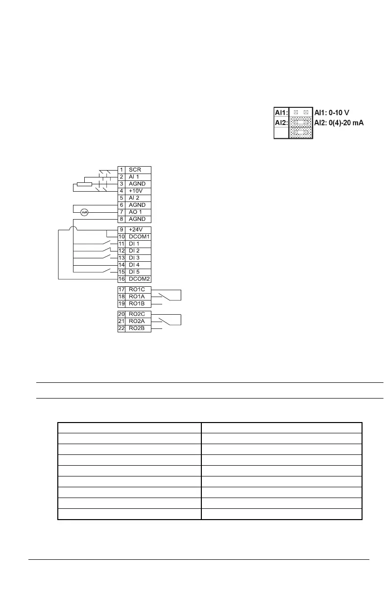
This macro is intended for applications where there is NO control panel available. It provides a
general purpose 3-wire I/O configuration.
The value of parameter 9902 is 0 (
FACTORY). DI 4 is connected.
*Note! DI 4 is used to configure ACS 400. It is read only once when power is connected. All
parameters marked with * are determined by the DI4 input.
Note! Stop input (DI2) deactivated: panel START/STOP button interlocked (local).
Factory (1) parameter values:
Input signals Output signals Jumper Setting
• Start, stop and direction
(DI1,2,3)
• An. output AO:
Frequency
• Analog reference (AI1) • Relay output 1: Fault
• Ramp pair 1/2 selection (DI5) • Relay output 2: Running
* 1001 EXT 1 COMMANDS 4 (DI1P,2P,P) 1402 RELAY OUTPUT 22 (RUN)
1002
EXT 2 COMMANDS 0 (NOT SEL) 1503 AO CONTENT MAX 60 Hz
1003
DIRECTION 3 (REQUEST) 1601 RUN ENABLE 0 (NOT SEL)
1102
EXT1/EXT2 SEL 6 (EXT1) 1604 FAULT RESET SEL 6 (START/STOP)
1103
EXT REF1 SELECT 1 (AI1) 2008 MAXIMUM FREQ 60 Hz
1105
EXT REF1 MAX 60 Hz 2105 PREMAGN SEL 0 (NOT SEL)
1106
EXT REF2 SELECT 0 (KEYPAD) 2201 ACC/DEC 1/2 SEL 5 (DI5)
* 1201 CONST SPEED SEL 0 (NOT SEL) 4001 PID GAIN 1.0
1401
RELAY OUTPUT 1 3 (FAULT (-1)) 4002 PID INTEG TIME 60 s
External Reference 1: 0...10 V <=> 0...50 Hz
Reference voltage 10 VDC
Not used
Output frequency 0...20 mA <=> 0...50 Hz
+24 VDC
Momentary activation with DI2 activated: Start
Momentary deactivation: Stop
Fwd/Rev: activate to reverse rotation direction
Has to be connected!*
Ramp pair selection. Activate to select ramp pair 2.
Relay output 1, programmable
Default operation: Fault => 17 connected to 18
Relay output 2, programmable
Default operation: Running => 20 connected to 22
http://nicontrols.com

 Loading...


