30 ACS 400 User’s Manual
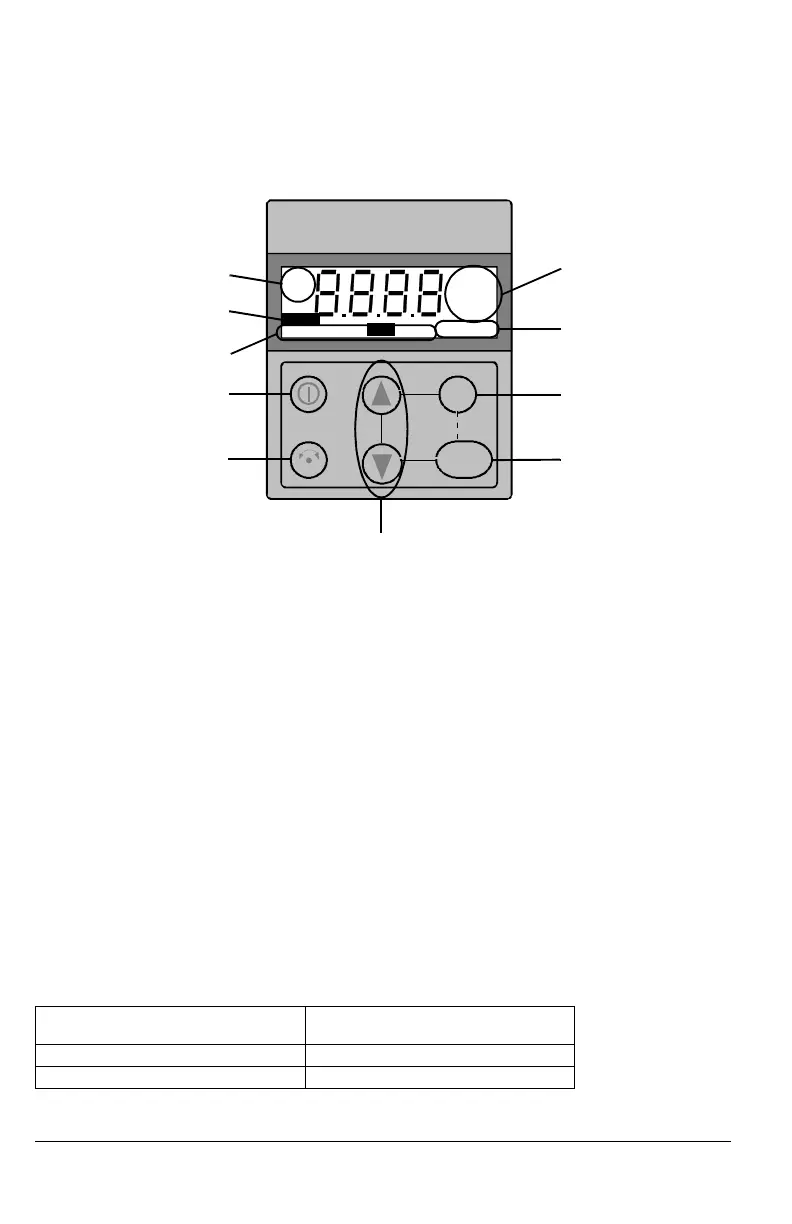
ACS100-PAN Control Panel
The control panel can be connected to and detached from the converter at any time.
Control Modes
The very first time the drive is powered up, it is controlled from the Control Terminals (remote
control, REM). The ACS 400 is controlled from the control panel when the drive is in local control
(LOC).
Switch to local control (LOC) by pressing and holding the MENU and ENTER buttons down
simultaneously until first Loc or later LCr is displayed:
• If the buttons are released while Loc is displayed, the panel frequency reference is set to the
current external reference and the drive is stopped.
• When LCr is displayed, the current run/stop status and the frequency reference are copied
from the user I/O.
Start and stop the drive by pressing the START/STOP button.
Change the shaft direction by pressing the REVERSE button (parameter 1003 must be set to
REQUEST).
Switch back to remote control (REM) by pressing and holding the MENU and ENTER buttons down
simultaneously until rE is displayed.
Shaft Direction
FWD / REV Visible Shaft direction is forward / reverse
Drive is running and at set point
FWD / REV Blinking rapidly Drive is accelerating / decelerating.
FWD / REV Blinking slowly Drive is stopped.
ENTER
MENU
LOC REM
mAVs
SETOUTPUTPAR MENU FWDREV
o
Crpm
%
REM
LOC
kHz
FAULT
LOC REM
Control modes
Active fault indicator
Display modes
START/STOP
REVERSE
Units
Shaft direction
MENU
ENTER
UP/DOWN
http://nicontrols.com

 Loading...


