ACS 400 User’s Manual 63
Application Macro PFC Control
This macro is intended for pump and fan control applications. For more information see “Appendix
B” on page 157.
The value of parameter 9902 is 8 (
PFC CONTROL).
Note! Parameter 2107
START INHIBIT should be 0 (OFF).
PFC parameter values:
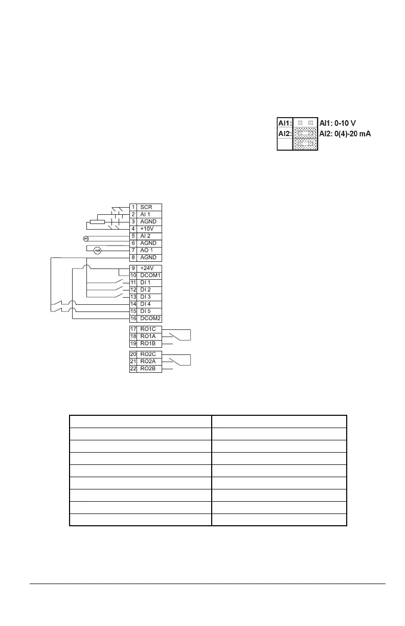
Input signals Output signals Jumper Setting
• Start and stop (DI1) • An. output AO: Frequency
• Analog reference (AI1) • Relay output 1: Speed
regulated motor
• Actual value (AI2) • Relay output 2: Auxiliary
motor
• Control location selection (DI3)
• Run enable (DI2)
1001
EXT 1 COMMANDS 1 (DI1) 1402 RELAY OUTPUT 229 (PFC)
1002
EXT 2 COMMANDS 1 (DI1) 1503 AO CONTENT MAX 62 Hz
1003
DIRECTION 1 (FORWARD) 1601 RUN ENABLE 2 (DI2)
1102
EXT1/EXT2 SEL 3 (DI3) 1604 FAULT RESET SEL 0 (KEYPAD)
1103
EXT REF1 SELECT 1 (AI1) 2008 MAXIMUM FREQ 62 Hz
1105
EXT REF1 MAX 62 Hz 2105 PREMAGN SEL 0 (NOT SEL)
1106
EXT REF2 SELECT 1 (AI1) 2201 ACC/DEC 1/2 SEL 0 (NOT SEL)
1201
CONST SPEED SEL 0 (NOT SEL) 4001 PID GAIN 2,5
1401
RELAY OUTPUT 1 29 (PFC) 4002 PID INTEG TIME 3 s
EXT1 (Manual) or EXT2 (PID/PFC) reference: 0...10 V
Reference voltage 10 VDC
Actual signal; 0...20 mA (PID)
Output frequency 0...20 mA <=> 0...52 Hz
+24 VDC
Start/Stop: Activate to start ACS 400.
Run enable: Deactivation always stops ACS 400
Interlock: Deactivation stops ACS 400
Interlock: Deactivation stops constant speed motor
Relay output 1, programmable
Default operation: Speed regulated motor switched on
Relay output 2, programmable
Default operation: Auxiliary motor switched on => 20
EXT1/EXT2 Selection: Activate to select PFC control
=> 17 connected to 19
connected to 22
http://nicontrols.com

 Loading...


