Resistor braking
164
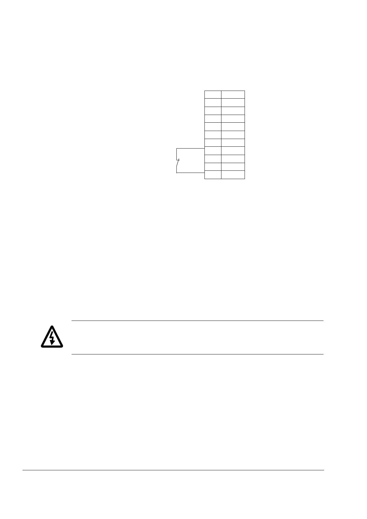
With Standard Control Program, wire the thermal switch as shown below. By default,
the drive will stop by coasting when the switch opens.
For other control programs, the thermal switch may be wired to a different digital
input. Programming of the input to trip the drive by “EXTERNAL FAULT” may be
needed. See the appropriate firmware manual.
Brake circuit commissioning
For Standard Control Program:
• Enable the brake chopper function (parameter 27.01).
• Switch off the overvoltage control of the drive (parameter 20.05).
• Check the resistance value setting (parameter 27.03).
• Frame size R6: Check the setting of parameter 21.09. If stop by coasting is
required, select OFF2 STOP.
For the use of the brake resistor overload protection (parameters 27.02...27.05),
consult an ABB representative.
WARNING! If the drive is equipped with a brake chopper but the chopper is not
enabled by parameter setting, the brake resistor must be disconnected because the
protection against resistor overheating is then not in use.
For settings of other control programs, see the appropriate firmware manual.
Note: Some brake resistors are coated with oil film for protection. At the start-up, the
coating burns off and produces a little bit of smoke. Ensure proper ventilation at the
start-up.
1DI1
2DI2
3DI3
4DI4
5DI5
6DI6
7+24VD
8+24VD
9 DGND1
10 DGND2
11 DIIL
Thermal switch
(standard in ABB re-
sistors)
RMIO:X22 or X2: X22
 Loading...

