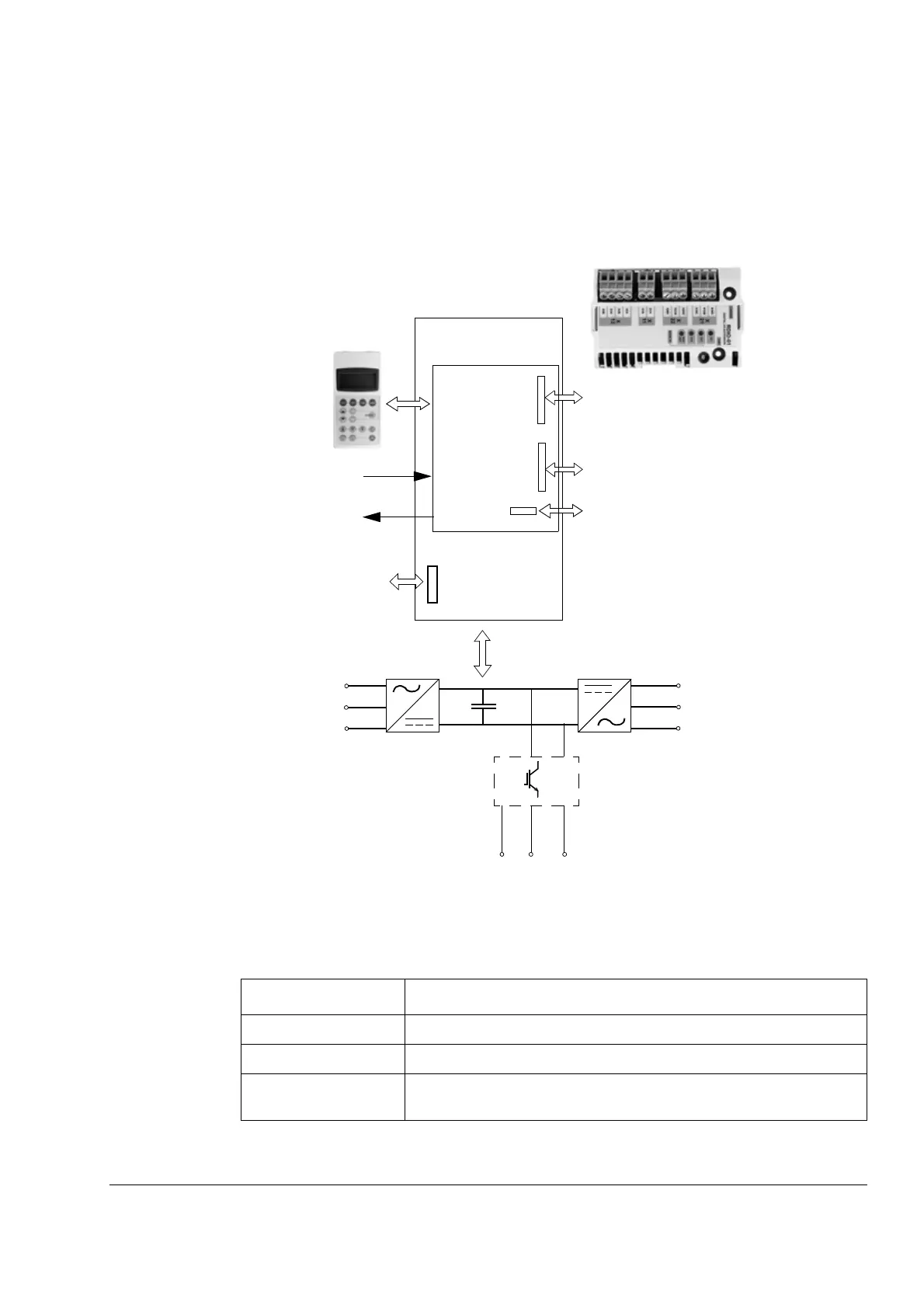
EasyManuals Logo

ABB ACS800-01-0070-3 User Manual

ABB ACS800-01-0070-3
174 pages
To Next Page IconTo Next Page
To Previous Page IconTo Previous Page
Page #27 background imageLoading...
Page #27 background image
Operation principle and hardware description
27
Main circuit and control
Diagram
This diagram shows the control interfaces and the main circuit of the drive.
Operation
This table describes the operation of the main circuit in short.
Component Description
six-pulse rectifier converts the three-phase AC voltage to DC voltage
capacitor bank energy storage which stabilizes the intermediate circuit DC voltage
IGBT inverter converts the DC voltage to AC voltage and vice versa. The motor
operation is controlled by switching the IGBTs.
Motor
control and
I/O board
(RMIO)
External control via
analogue/digital
inputs and outputs
Input power
Output power
Option module 1: RMBA, RAIO, RDIO,
RDNA, RLON, RIBA, RPBA, RCAN,
RCNA, RMBP, RETA, RECA, REPL, RRIA
or RTAC
Option module 2: RTAC, RAIO, RRIA or
RDIO
DDCS communication option module 3:
RDCO-01, RDCO-02 or RDCO-03
R- UDC+ UDC-
R+
Brake chopper in frame sizes R2 and R3
and in 690 V units of frame size R4
(optional in other frame sizes)
X41Prevention of unexpected start -up
(AGPS board) or
Safe torque off (ASTO board)
Drive

Table of Contents

Questions and Answers:

Question and Answer IconNeed help?

Do you have a question about the ABB ACS800-01-0070-3 and is the answer not in the manual?

ABB ACS800-01-0070-3 Specifications

General IconGeneral
BrandABB
ModelACS800-01-0070-3
CategoryDC Drives
LanguageEnglish

Related product manuals