EasyManua.ls Logo

ABB IRB 120 User Manual

ABB IRB 120
272 pages
To Next Page IconTo Next Page
To Previous Page IconTo Previous Page
Page #23 background imageLoading...
Page #23 background image
Non-voltage related risks
Make sure that no one else can turn on the power to the controller and robot
while you are working with the system. A good method is to always lock the
main switch on the controller cabinet with a safety lock.
Safety zones, which must be crossed before admittance, must be set up in
front of the robot's working space. Light beams or sensitive mats are suitable
devices.
Turntables or the like should be used to keep the operator out of the robot's
working space.
If the robot is installed at a height, hanging, or other than standing directly
on the floor, there may be additional risks than those for a robot standing
directly on the floor.
The axes are affected by the force of gravity when the brakes are released.
In addition to the risk of being hit by moving robot parts, there is a risk of
being crushed by the parallel arm (if there is one).
Energy stored in the robot for the purpose of counterbalancing certain axes
may be released if the robot, or parts thereof, are dismantled.
When dismantling/assembling mechanical units, watch out for falling objects.
Be aware of stored heat energy in the controller.
Never use the robot as a ladder, which means, do not climb on the motors
or other parts during service work. There is a serious risk of slipping because
of the high temperature of the motors and oil spills that can occur on the
robot. There is also a risk of the robot being damaged.
To be observed by the supplier of the complete system
When integrating the robot with external devices and machines:
The supplier of the complete system must ensure that all circuits used in the
safety function are interlocked in accordance with the applicable standards
for that function.
The supplier of the complete system must ensure that all circuits used in the
emergency stop function are interlocked in a safe manner, in accordance
with the applicable standards for the emergency stop function.
Complete robot
DescriptionSafety risk
CAUTION
Motors and gearboxes are HOT after running
the robot! Touching motors and gearboxes
may result in burns!
With a higher environment temperature, more
surfaces on the manipulator will get HOT and
may also result in burns.
Hot components!
Continues on next page
Product manual - IRB 120 23
3HAC035728-001 Revision: N
© Copyright 2009-2017 ABB. All rights reserved.
1 Safety
1.2.4.1 Safety risks during installation and service work on manipulators
Continued

Table of Contents

Other manuals for ABB IRB 120

Question and Answer IconNeed help?

Do you have a question about the ABB IRB 120 and is the answer not in the manual?
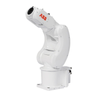
ABB IRB 120 Specifications

General IconGeneral
TypeIndustrial Robot
Axes6
Payload3 kg
Reach580 mm
Repeatability±0.01 mm
Weight25 kg
ProtectionIP40
ControllerIRC5 Compact
Power Consumption0.25 kW
MountingFloor, Wall
Operating Temperature5°C to 45°C

Summary

Safety

Introduction to safety information

Overview of safety information categories: general aspects, signals, and specific instructions.

General safety information

Details general safety information for installation, maintenance, and repair personnel.

Safety signals and symbols

Explains safety signals (DANGER, WARNING, CAUTION) and symbols used in the manual and on the product.

Safety related instructions

Provides specific safety instructions and warnings for dangerous steps in procedures.

Installation and commissioning

On-site installation

Details procedures for lifting, orienting, securing, and fitting equipment onto the robot.

Electrical connections

Details robot cabling, connection points, and bending radius for static floor cables.

Maintenance

Maintenance schedule

Specifies maintenance intervals and activities (inspection, replacement, cleaning) based on a schedule.

Repair

Motors and motors with gearboxes

Covers procedures for replacing motors and gearboxes for individual axes (1 through 6).

Gearboxes

Covers gearbox replacement for individual axes (1 through 6), often referring to motor replacement.

Calibration

Updating revolution counters

Describes how to perform a rough calibration by updating revolution counters using the FlexPendant.

Calibrating with Axis Calibration method

Details the Axis Calibration method, including its description and procedure on the FlexPendant.

Calibrating with manual calibration method

Describes manual calibration procedures for individual axes using calibration pins and the FlexPendant.

Spare parts

Related product manuals