2.3.3 Orienting and securing the robot
Introduction
This section details how to orient and secure the robot to the foundation or base
plate in order to run the robot safely. The requirements made on the foundation
are shown in sections:
• Loads on foundation, robot on page 57
• Requirements, foundation on page 58.
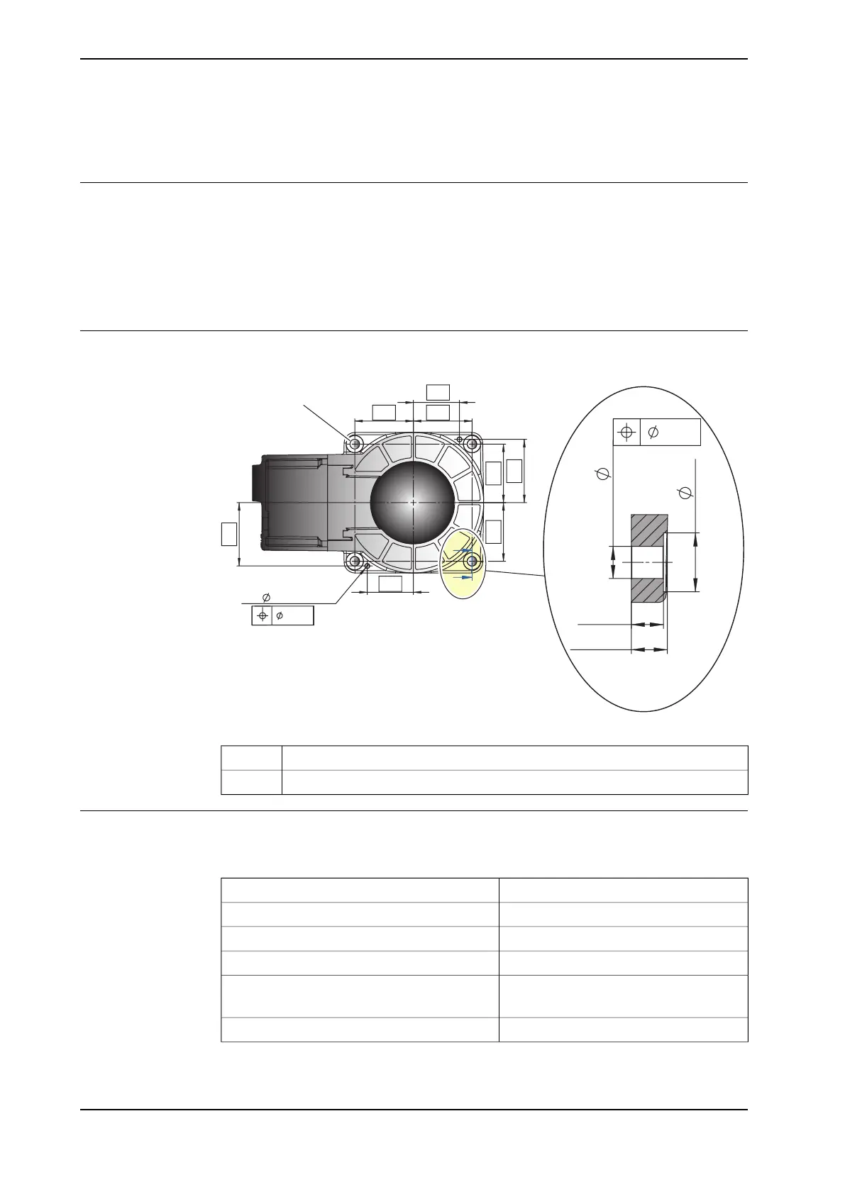
Hole configuration, base
The illustration shows the hole configuration used when securing the robot.
0.5
E-E
4x
22
12
12
4x
4x
4x14.3
0.15
2x
75
+0.018
6
59
0H8
81
81
75 75
75
59
A
B
E
E
xx0900000162
Holes for attachment screws (4 pcs)A
Holes for pins (2 pcs)B
Specification, attachment screws and pins
The table specifies the type of securing screws and washers to be used to secure
the robot directly to the foundation. It also specifies the type of pins to be used.
M10x25Suitable screws
4 pcsQuantity
8.8-A3FQuality
10 mmSuitable washer
2 pcs, D6x20Guide pins
ISO 2338-6 m6x30 - A1
35 NmTightening torque
Continues on next page
70 Product manual - IRB 120
3HAC035728-001 Revision: N
© Copyright 2009-2017 ABB. All rights reserved.
2 Installation and commissioning
2.3.3 Orienting and securing the robot
 Loading...