2.4.2 Mechanically restricting the working range
Location of mechanical stops
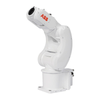
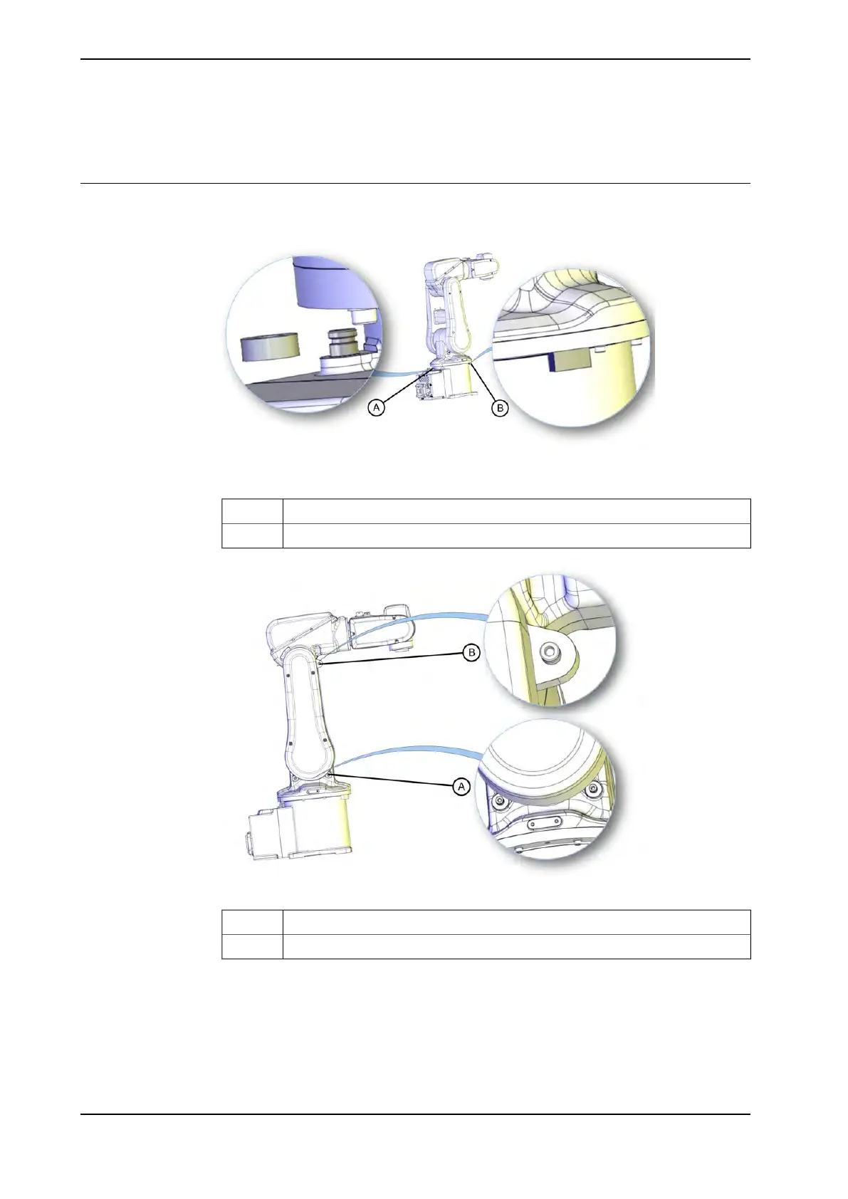
The figures shows where the mechanical stops are placed on the robot.
xx1000000002
Mechanical stop axis 1 (base)A
Mechanical stop axis 1 (swing plate)B
xx0900000583
Mechanical stop axis 2 (swing housing)A
Mechanical stops axis 2 (upper arm)B
Continues on next page
82 Product manual - IRB 120
3HAC035728-001 Revision: N
© Copyright 2009-2017 ABB. All rights reserved.
2 Installation and commissioning
2.4.2 Mechanically restricting the working range
 Loading...