Tension Electronics PFEA113, User Manual
Section E.4 Installation Requirements
3BSE029382R0101 Rev C E-3
E.4 Installation Requirements
To achieve the specified accuracy, the best possible reliability and long-term stability, install the
load cells in accordance with the requirements below.
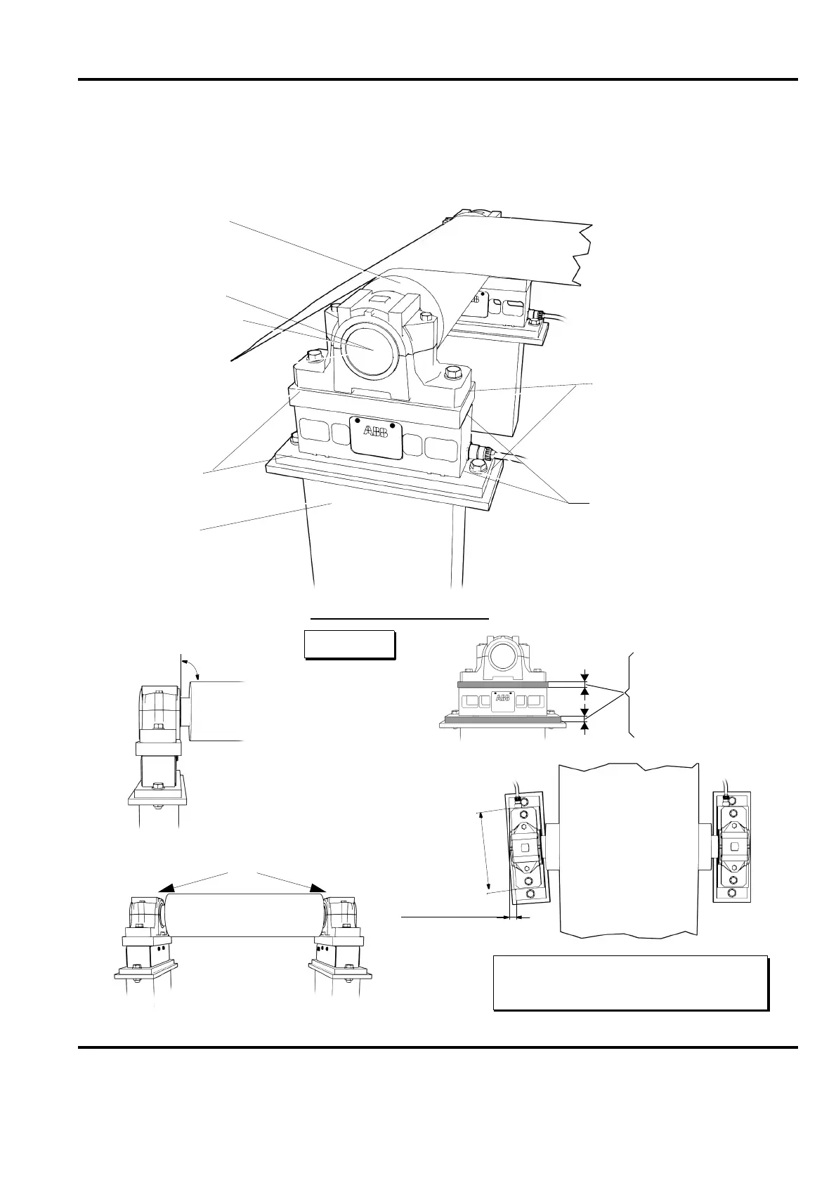
Figure E-1. Installation Requirements
Shims may be placed
between the upper adapter
plate and the bearing housing
and between the lower adapter
Alignment of the load cells
the load cell.
immediately above or below
Shims must not be placed
plate and the foundation.
Web
a)
PFTL 101A/AE/AER 230 mm (9 in.)
PFTL 101B/BE/BER 360 mm (14 in.)
a)
a)
For correct tightening torques,
see table E-1.
1.0 mm (0.04 in.)
In level
Adapter plate thickness
PFTL 101A
PFTL 101B
min. 35 mm (1.38 in.)
min. 30 mm (1.18 in.)
90°
mm (inches)
Dynamically balanced
Self aligning bearings
Mounting surface
Stable foundation
If the measuring roll is driven,
always consult ABB to ensure
0.05 mm (0.002 in.)
Grade G-2.5 ISO 1940-1.
that fulfills at least
measuring roll
of disturbances.
a solution with minimized risk
must be flat within
use SKF CARB bearings,
sliding spherical roller
Use fixed spherical roller
or as a second choice,
To allow axial expansion,
the shaft.
bearings at one end of
bearings at the other
end of the shaft.

 Loading...