Tension Electronics PFEA113, User Manual
Section 2.10 Connecting Analog Inputs (AI1-AI2)
3BSE029382R0101 Rev C 2-13
2.10 Connecting Analog Inputs (AI1-AI2)
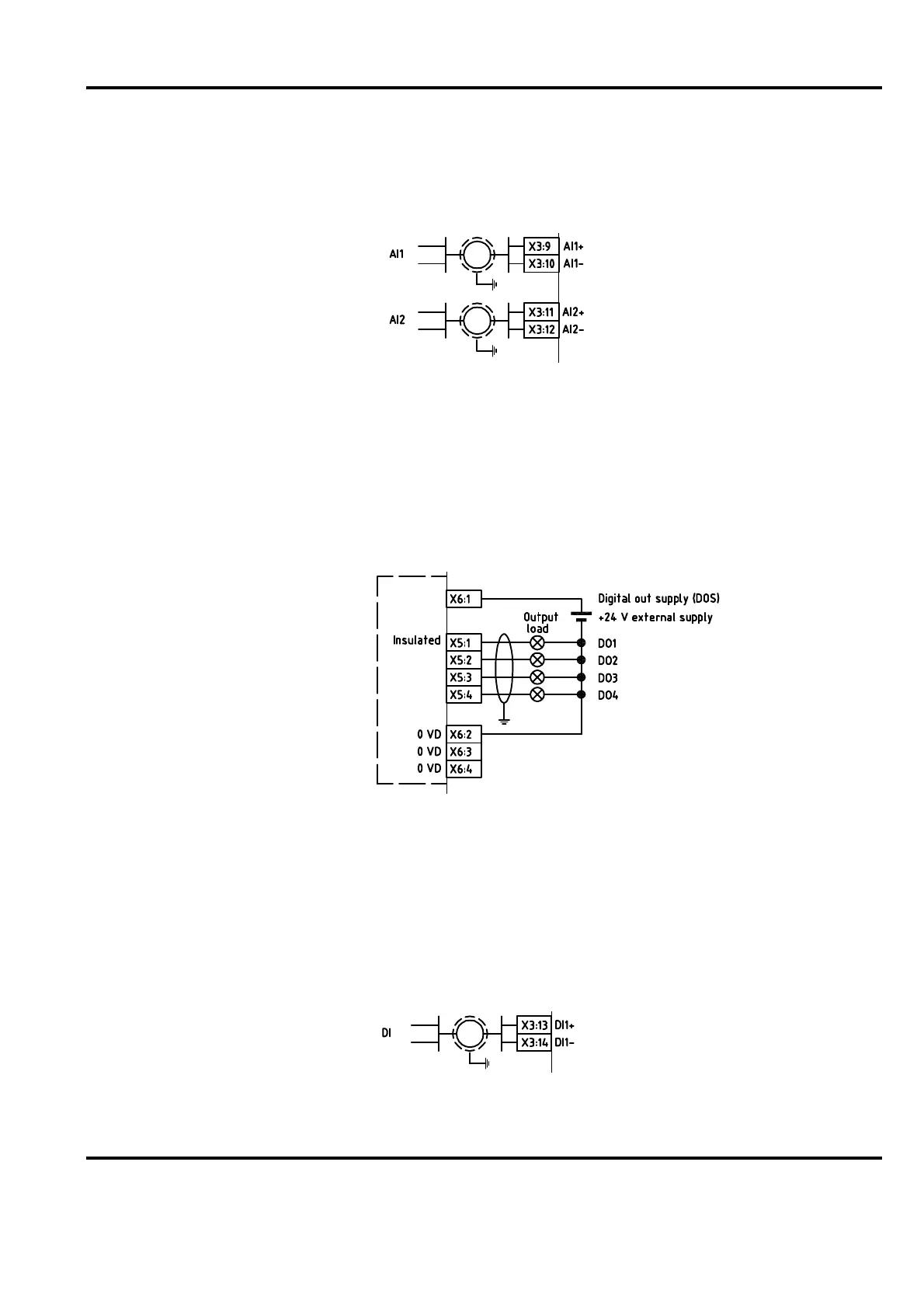
The two analog inputs, AI1 and AI2, are differential inputs with a signal range of 0-10 V.
Figure 2-13. Connecting Analog Inputs
2.11 Connecting Digital Outputs (DO1-DO4)
The four digital outputs, DO1-DO4, are insulated as a group. See Figure 2-14.
The digital outputs are current driving and can be supplied from an external 24 V DC or from
the 24 V DC supply used for PFEA113.
The current at state “1” is maximum 0.1 A per output.
Figure 2-14. Connecting Digital Outputs
2.12 Connecting the Digital Input (DI)
The digital input is a differential input with the following data:
Passive: -36 V to +5 V
Active: >16 V (maximum +36 V)
Figure 2-15. Connecting the Digital Input

 Loading...