 Loading...
Do you have a question about the ABB PFEA 113 and is the answer not in the manual?
| ABB Type Designation | PFEA113 |
|---|---|
| Category | Measuring Instruments |
| Manufacturer | ABB |
| Output Signal | 4-20 mA, HART |
| Model | PFEA 113 |
| Protection Class | IP67 |
Details critical safety precautions for personnel and equipment.
Lists crucial safety guidelines to follow before installation work.
Provides references for load cell installation requirements and instructions.
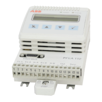
Covers the installation process for the electronic unit itself.
Details recommendations for selecting and routing cables correctly.
Describes mounting procedures for both IP 65 and IP 20 versions.
Explains the critical earthing procedures for proper operation and safety.
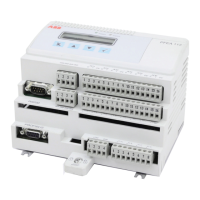
Identifies and describes the various connectors on the PFEA113 unit.
Outlines the process for connecting the load cells to the system.
Lists crucial safety guidelines to follow before commissioning work.
Offers a sequential guide for commissioning the web tension system.
Guides through essential initial settings like language and units.
Details a simplified setup process for basic measurements.
Describes how to verify the correct polarity of load cell signals.
Explains how to perform a functional test on the load cells.
Guides users through the comprehensive system setup process.
Provides a detailed step-by-step guide for the complete setup.
Covers settings for language, units, and decimals for display.
Details settings for load cell combination and gain scheduling.
Explains how to define the measurement object type based on load cell configuration.
Describes how to set the nominal load for the load cells.
Explains the procedure for compensating load cell zero signals and tare weight.
Details methods for determining and setting the wrap gain.
Lists crucial safety guidelines to follow before operating the system.
Provides instructions for safely starting up and shutting down the system.
Describes the system's state during continuous operation.
Describes the menus accessible to the operator for monitoring and control.
Details how web tension values are displayed for different roll configurations.
Describes how to interpret and respond to system error and warning messages.
Outlines regular checks and preventive measures to ensure system reliability.
Lists crucial safety guidelines to follow when tracing faults.
Details a systematic approach to identifying and resolving faults.
Explains the meaning of detected errors and warnings.
Provides a guide to diagnosing faults based on symptoms and recommended actions.
Details specific warnings and errors and their troubleshooting steps.
Provides a step-by-step procedure for replacing load cells.
Presents detailed technical specifications for the PFEA113 electronics.
Provides a procedural guide for designing the load cell installation.
Details the specific requirements for accurate and stable load cell installation.
Covers mounting options and methods for calculating forces and wrap gain.
Details force calculation methods when using a single load cell.
Provides detailed instructions for physically mounting the load cells.
Provides a procedural guide for designing the load cell installation.
Details the specific requirements for accurate and stable load cell installation.
Provides detailed instructions for physically mounting the load cells.
Provides a procedural guide for designing the load cell installation.
Provides detailed instructions for physically mounting the load cells.
Provides a procedural guide for designing the load cell installation.
Provides detailed instructions for physically mounting the load cells.
Provides a procedural guide for designing the load cell installation.
Provides detailed instructions for physically mounting the load cells.
Provides a procedural guide for designing the load cell installation.
Provides detailed instructions for physically mounting the load cells.
