Tension Electronics PFEA113, User Manual
Section 3.14.1 Insulation Amplifier PXUB 201
3BSE029382R0101 Rev C 3-49
4. Set the switches S1 and S2.
5. Slide back the top lid to locked position.
6. Remount the insulation amplifier on the DIN rail.
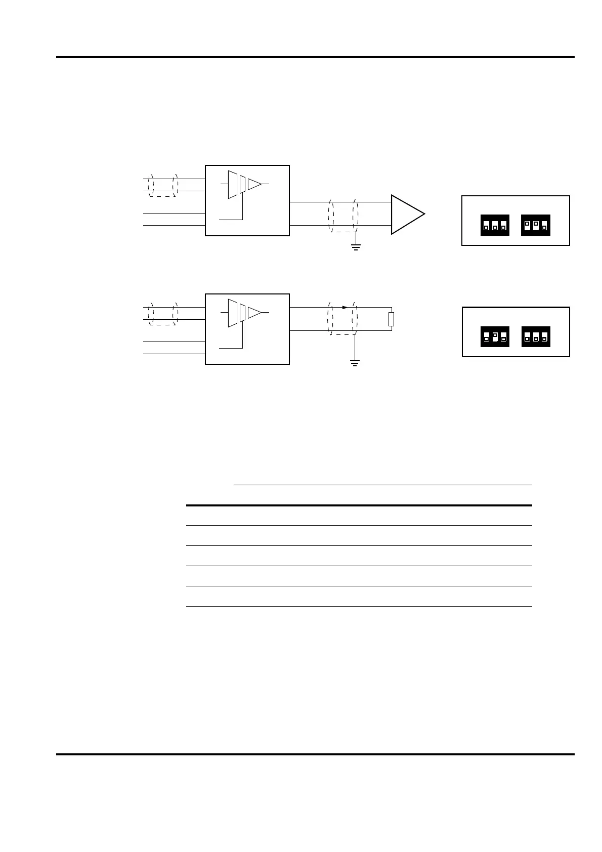
Figure 3-28. Typical Connection of the Insulation Amplifier
Table 3-7. Setting of Input and Output Range
Default
Range S1 S2
Input Output 1 2 3 1 2 3
× 0 to ±10 V 0 to ±10 V × ×
0 to 5 V 4 to 20 mA ×
0 to 10 V 4 to 20 mA ×
0 to 5 V 0 to 20 mA × ×
0 ± 10 V 0 ± 20 mA ×
Earth
Earth
Signal
0 V
+24 V
0 V
+
-
+
-
+
5
6
3
4
7
8
Signal
0 V
+24 V
0 V
+
-
+
-
+
–
5
6
3
4
7
8
PXUB 201
PXUB 201
–
1 2 3
ON
S1
1 2 3
ON
S2
1 2 3
ON
S1
1 2 3
ON
S2
Output: 4 to 20 mA
Input: 0 to 10 V
Output: 0 to ± 10 V
Input: 0 to ± 10 V

 Loading...