115
21. Appendix C: Tripping time indication
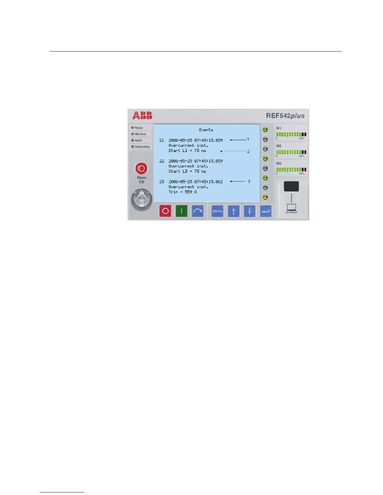
The example below shows and explains the information on the Events page of the
HMI. It refers to events generated by Overcurrent Instantaneous protection function.
The test is performed with a fault current around 10 times of the current threshold
setting value, simulating a two-phase fault between phase L1 and phase L3.
A051660
Fig. 21.-1 Start/Trip events
Event number 21:
The Overcurrent Instantaneous protection function detects the system fault
condition on phase L1 at the absolute time 25/05/2006, 07:45:15.859. The time
stamp is indicated by arrow 1, see Fig. 21.-1.
Event number 22:
The Overcurrent Instantaneous protection function detects the system fault
condition on phase L3 at the same absolute time 25/05/2006, 07:45:15.859.
Event number 23:
The trip by the above-mentioned protection function is released at the absolute time
25/05/2006, 07:45:15.862, which is indicated by arrow 3, see Fig. 21.-1.
As long as the current is not interrupted, the start signal remains active. Arrow 2
indicates that the current is flowing for a time duration of 73 ms.
Multifunction Protection and Switchgear Control Unit
Operator's manual
REF 542plusREF 542plus
1MRS755869
 Loading...