81
A051457
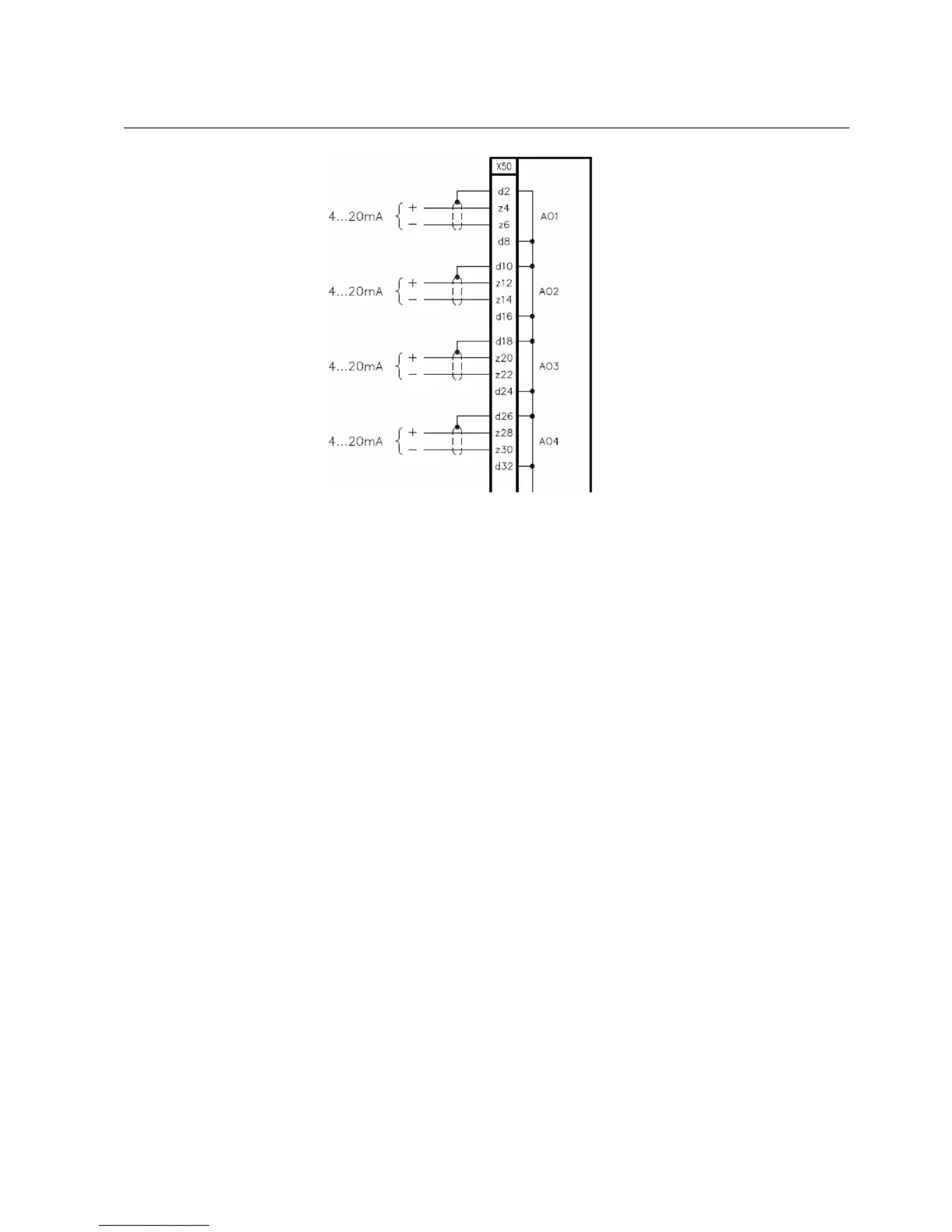
Fig. 19.3.1.-1 0/4-20 mA analog outputs (Version 2.x since 06/2006)
19.3.2. Analog inputs 4-20 mA
When present, the 4-20 mA analog input module uses connector X50. Sensor’s
connections are shown in Fig. 19.3.2.-1 X51 and X52 are service interfaces of no
use for the user. The output contact BO1 is for the future use.
Multifunction Protection and Switchgear Control Unit
Operator's manual
REF 542plusREF 542plus
1MRS755869
 Loading...