8
X1
Zm
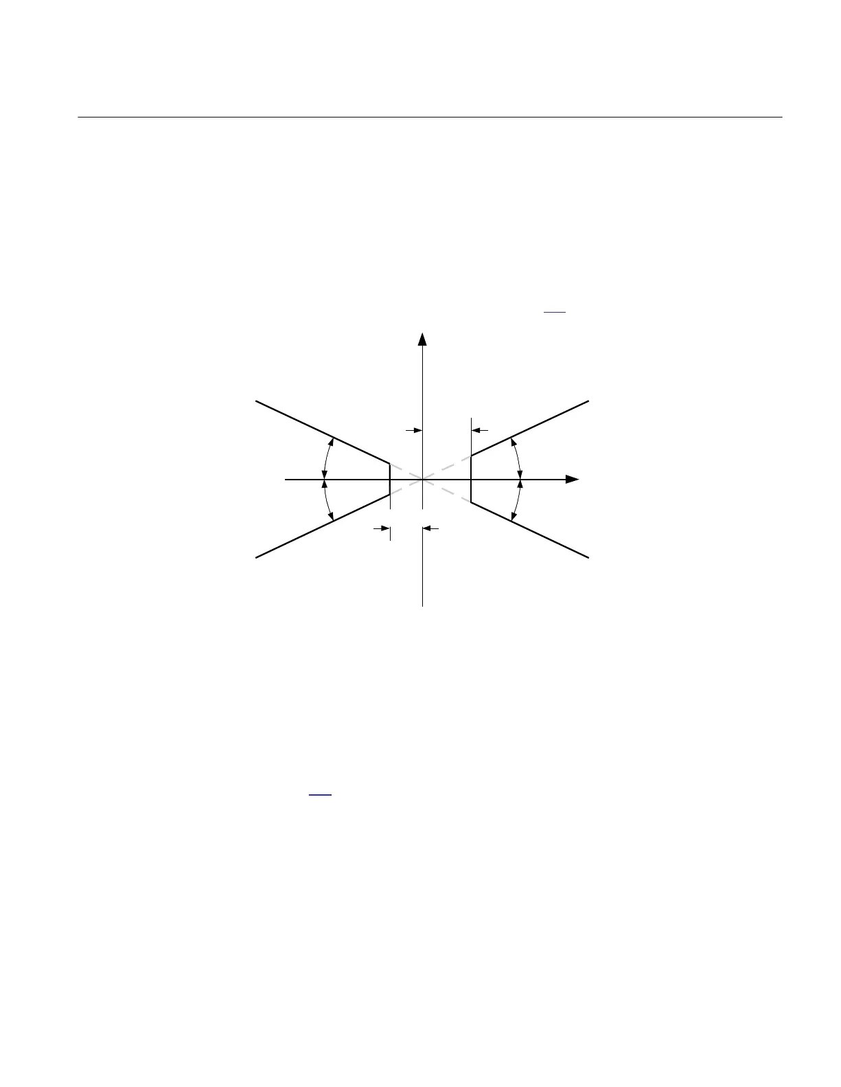
8.2.3.2 Resistive reach with load encroachment characteristic
M13142-312 v4
The procedure for calculating the settings for the load encroachment consist basically
to define the load angle LdAngle, the blinder RLdFwd in forward direction and blinder
RLdRev in reverse direction, as shown in figure
119.
R
X
RLdFwd
RLdRev
LdAngle
LdAngle
LdAngle
en05000226_ansi.vsd
LdAngle
ANSI05000226 V1 EN-US
Figure 119: Load encroachment characteristic
The load angle LdAngle is the same in forward and reverse direction, so it could be
suitable to begin to calculate the setting for that parameter. Set the parameter to the
maximum possible load angle at maximum active load. A value bigger than 20° must
be used.
The blinder in forward direction, RLdFwd, can be calculated according to
equation
108.
1MRK 504 163-UUS A Section 8
Impedance protection
Transformer protection RET670 2.2 ANSI 255
Application manual

 Loading...


