For controllable gates, settable timers and SR flip-flops with memory, the setting
parameters are accessible via the local HMI or via the PST tool.
17.6.2.1 Configuration
GUID-D93E383C-1655-46A3-A540-657141F77CF0 v4
Logic is configured using the ACT configuration tool in PCM600.
Execution of functions as defined by the configurable logic blocks runs according to a
fixed sequence with dif
ferent cycle times.
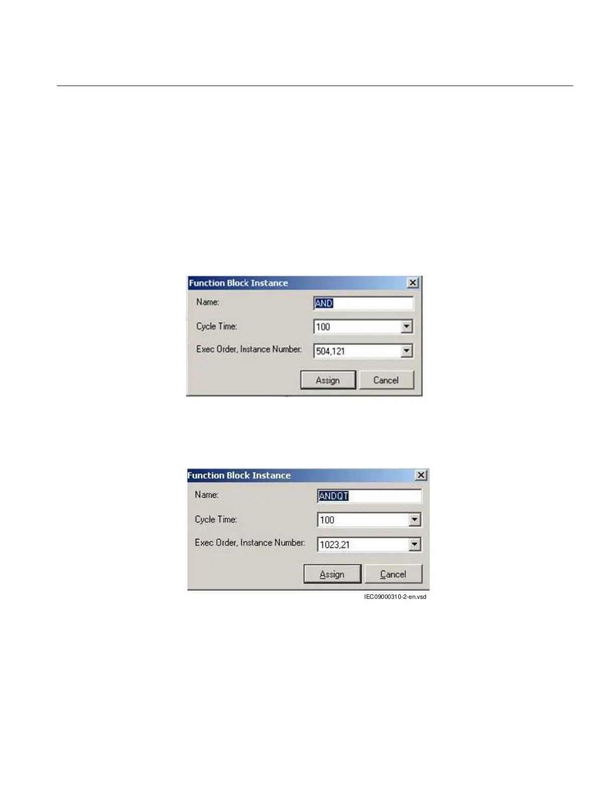
For each cycle time, the function block is given an serial execution number. This is
shown when using the ACT configuration tool with the designation of the function
block and the cycle time, see example below.
IEC09000695 V2 EN-US
Figure 398: Example designation, serial execution number and cycle time for logic
function
IEC09000310 V2 EN-US
Figure 399: Example designation, serial execution number and cycle time for logic
function that also propagates timestamp and quality of input signals
The execution of different function blocks within the same cycle is determined by the
order of their serial execution numbers. Always remember this when connecting two or
more logical function blocks in series.
1MRK 504 163-UUS A Section 17
Logic
Transformer protection RET670 2.2 ANSI 849
Application manual

 Loading...


