SEMOD154680-267 v2
A
B
Z<
Z<
Z<
C
T
IC
IA
IB
-IB
en05000224.vsd
DOCUMENT11524-IMG869 V1 EN-US
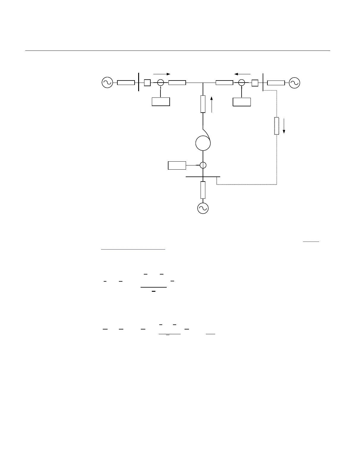
Figure 147: Example of tapped line with Auto transformer
This application gives rise to similar problem that was highlighted in section
"Fault
infeed from remote end" that is, increased measured impedance due to fault current
infeed. For example for faults between the T point and B station the measured
impedance at A and C will be
DOCUMENT11524-IMG3509 V3 EN-US (Equation 173)
2
2
1
A C
C Trf CT TB
C
I I V
Z Z Z Z
V
I
=
æ ö
+
æ ö
+ + × ×
ç ÷
ç ÷
è ø
è ø
EQUATION1783-ANSI V1 EN-US (Equation 174)
Where:
ZAT and ZCT is the line impedance from the B respective C station to the T point.
IA and IC is fault current from A respective C station for fault between T and B.
V2/V1 Transformation ratio for transformation of impedance at V1 side of the transformer to
the measuring side
V2 (it is assumed that current and voltage distance function is
taken from V2 side of the transformer).
Section 8 1MRK 504 163-UUS A
Impedance protection
304 Transformer protection RET670 2.2 ANSI
Application manual

 Loading...


