en04000499_ansi.vsd
189OPTR (bay 1/sect.A1)
S1DC_OP
VPS1_DC
EXDU_BB
AND
189OPTR (bay n/sect.A1)
. . .
. . .
. . .
VP189TR (bay 1/sect.A1)
VP189TR (bay n/sect.A1)
EXDU_DB (bay 1/sect.A1)
EXDU_DB (bay n/sect.A1)
. . .
. . .
. . .
. . .
. . .
. . .
AND
AND
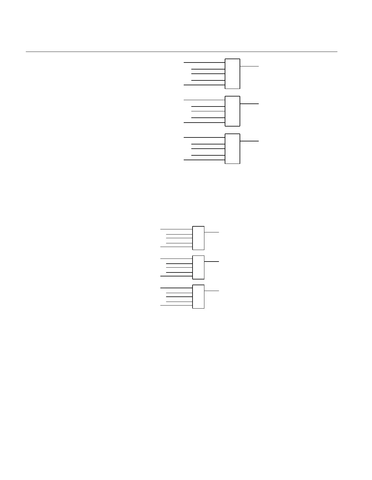
ANSI04000499 V1 EN-US
Figure 346: Signals from double-breaker bays in section A1 to a bus-section
disconnector
For a bus-section disconnector, these conditions from the A2 busbar section are valid:
en04000500_ansi.vsd
189OPTR (bay 1/sect.A2)
S2DC_OP
VPS2_DC
EXDU_BB
AND
189OPTR (bay n/sect.A2)
. . .
. . .
. . .
VP189TR (bay 1/sect.A2)
VP189TR (bay n/sect.A2)
EXDU_DB (bay 1/sect.A2)
EXDU_DB (bay n/sect.A2)
. . .
. . .
. . .
. . .
. . .
. . .
AND
AND
ANSI04000500 V1 EN-US
Figure 347: Signals from double-breaker bays in section A2 to a bus-section
disconnector
For a bus-section disconnector, these conditions from the B1 busbar section are valid:
Section 15 1MRK 504 163-UUS A
Control
742 Transformer protection RET670 2.2 ANSI
Application manual

 Loading...


