11
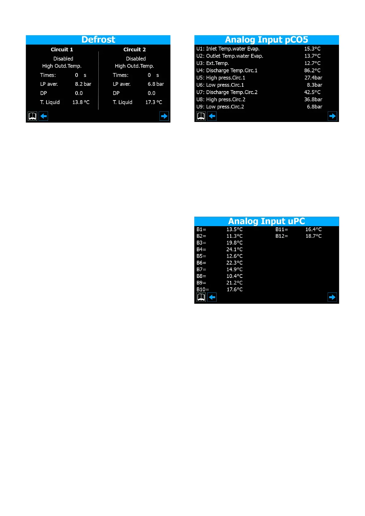
4.4 DEFROSTING STATUS
1. Indicates the current defrosting status on circuit 1. The possible values are:
— Disabled = No defrosting active;
— Bypass = Indicates that the bypass phase is currently active, following compres-
sor start-up;
— Decay calculation = Indicates that the pressure decay calculation is currently
in progress;
— Cycle reversal standby = Indicates that the pause is active, prior to the cycle
valve reversal;
— Defrosting start-up = Indicates that the defrosting cycle is beginning;
— Defrosting in progress = Indicates that the defrosting cycle is currently in pro-
gress;
— Defrosting end = Indicates that the defrosting cycle is ending;
— First defrosting = Indicates that the rst defrosting after a blackout is active;
2. Gives additional information about the defrosting status of circuit 1. This in-
formation may be:
— High outside temperature = Indicates that the outside air temperature is above
the defrosting enabling threshold;
— Circuit OFF = Indicates that the circuit compressors are switched o and de-
frosting is disabled;
— BP above limit threshold = Indicates that the low pressure value ("BP") is above
the limit threshold for triggering the defrosting cycle;
— Min time between defrosting cycles = Indicates that the defrosting cycle is cur-
rently disabled in order to respect the minimum time between two cycles;
— CP start-up = Indicates that the compressor has just been started up and the
bypass time before calculating the pressure decay is in progress;
— New BP reference = Indicates that a new low pressure value has been taken as
the reference for calculating the decay;
— Start-up for BP limit = Indicates that defrosting has been activated in order to
exceed the low pressure limit threshold;
— Start-up for P-delta = Indicates that defrosting has been activated in order to
exceed the low pressure decay value;
— Liquid temp. OK = Indicates that the liquid temperature has exceeded the
threshold for determining the end of the defrosting cycle;
— Min. defrosting times = Indicates that defrosting continues until the minimum
set time has been exceeded, even if the output conditions have already been
reached;
— Standby for other circuit = In the case of a single ventilation unit, indicates the
phase in which the circuit that ends the defrosting cycle rst switches o, wait-
ing for the other circuit to end too;
— First start-up bypass = Indicates that the rst defrosting cycle after a blackout
can only start after the compressor has been working for a specic time;
— Low liquid temp. = Indicates that the liquid temperature is below the threshold
for determining the end of the defrosting cycle;
— Start-up for TGP = Indicates that the defrosting cycle has been activated be-
cause the temperature threshold for the force gas has been exceeded;
— Forced = In the case of a single ventilation unit, indicates that the circuit has
been forced to defrost by the other circuit.
3. Indicates the defrosting times for circuit 1
4. Indicates the average low pressure value on circuit 1
5. Indicates the accumulated P-delta for determining defrosting activation on
circuit 1
6. Indicates the liquid temperature value for determining the defrosting end on
circuit 1
7. The same as point (1), but with reference to circuit 2 (if installed)
8. The same as point (2), but with reference to circuit 2 (if installed)
9. Indicates the defrosting times for circuit 2 (if installed)
10. Indicates the average low pressure value on circuit 2 (if installed)
11. Indicates the accumulated P-delta for determining defrosting activation on
circuit 2 I(if installed)
12. Indicates the liquid temperature value for determining the defrosting end on
circuit 2 (if installed)
4.5 PCO5 ANALOGUE INPUT STATUS
1. Indicates the current temperature value measured on the evaporator inlet
2. Indicates the current temperature value measured on the evaporator outlet
3. Indicates the current outside air temperature
4. Indicates the current temperature measured on the high-pressure side of cir-
cuit 1
5. Indicates the current high-pressure value of circuit 1
6. Indicates the current low-pressure value of circuit 1
7. Indicates the current temperature measured on the high-pressure side of cir-
cuit 2
8. Indicates the current high-pressure value of circuit 2
9. Indicates the current low-pressure value of circuit 2
4.6 UPC ANALOGUE INPUT STATUS
1. Not used
2. Not used
3. Not used
4. Not used
5. Not used
6. This gure may refer to various values, depending on the type of unit:
— Unit with total heat recovery = Indicates the temperature of the water entering
the total recovery unit;
— Free-cooling unit = Indicates the inlet temperature on the Free-cooling unit;
7. This gure may refer to various values, depending on the type of unit:
— Unit with total recovery = Indicates the temperature of the water leaving the
total recovery unit (heat exchanger 1);
— Free-cooling unit (glycol-free) = Indicates the outlet temperature on the
Free-cooling unit (glycol-free);
8. This gure may refer to various values, depending on the type of unit:
— Unit with total recovery = Indicates the temperature of the water leaving the
total recovery unit (heat exchanger 2);
— Free-cooling unit = Indicates the temperature measured by the probe on the
intermediate heat exchanger;
9. Indicates the current temperature value for water leaving evaporator 2
10. Not used
11. Indicates the current water temperature on the common evaporator outlet
12. Not used
 Loading...