17
7.5 CONFIGURING THE THERMOSTAT AND THE TYPE OF
OPERATING SETPOINT
— Indicates which probe should be used for the thermostat control of the pro-
cessed water. The value can be:
OUTLET (U2) = thermostat control will be carried out on the evaporator outlet
probe;
INLET (U1) = thermostat control will be carried out on the evaporator inlet probe;
COMMON OUTLET PROBE = thermostat control will be carried out on the probe on
the common outlet of the evaporators (if envisaged);
ACCUMULATION (U1) = thermostat control will be carried out on the accumulation
tank probe (if installed);
— Indicates the type of adjustment to be applied to the thermostat control. The
value can be:
PROP+INT = PROPORTIONAL + INTEGRAL adjustment will be used;
PROPORTIONAL = PROPORTIONAL adjustment will be used;
— Indicates the value assigned to the integration time, used to calculate the in-
tegral error
— Used to select the type of set-point to be used for cooling. The possible values
are:
FIXED SET-POINT = the adjustment will use a xed set-point with a value dened by
the user on the relative page of the "System menu";
CLIMATE CURVE = the adjustment will be made automatically, calculating the set-
point on the basis of the outside temperature (according to the setting made on the
"climate curve" page of this menu);
— Indicates the value assigned to the dierential used in cooling mode
— Used to select the type of set-point to be used for heating. The possible values
are:
FIXED SET-POINT = the adjustment will use a xed set-point with a value dened by
the user on the relative page of the "System menu";
CLIMATE CURVE = the adjustment will be made automatically, calculating the set-
point on the basis of the outside temperature (according to the setting made on the
"climate curve" page of this menu);
— Indicates the value assigned to the dierential used in heating mode
— Indicates the value assigned to the dierential used for heat recovery
— Indicates the maximum temperature of the water leaving the recovery unit, be-
yond which recovery mode is forcedly abandoned.
7.6 CONFIGURING THE CLIMATE CURVE
1. Indicates the current value of the cooling set-point, calculated on the basis of
the climate curve
2. Indicates the value to be assigned to the compensation set-point for the
climate curve used in cooling mode. This value will be subtracted from the
set-point dened by the user in the system menu, and associated with the
maximum outside air temperature specied in parameter (4)
3. Indicates the minimum outside air temperature (the starting point of the cli-
mate curve in cooling mode) to which set-point 1 (cooling) (dened by the
user in the system menu) must correspond
4. Indicates the maximum outside air temperature (the end point of the climate
curve in cooling mode) to be associated with the result of the subtraction of
set-point 1 (dened by the user in the system menu) from the compensation
set-point dened in parameter (2)
5. Indicates the current value of the heating set-point, calculated on the basis of
the climate curve
6. Indicates the value to be assigned to the compensation set-point for the cli-
mate curve used in heating mode. This value will be subtracted from the set-
point dened by the user in the system menu, and associated with the maxi-
mum outside air temperature specied in parameter (7)
7. Indicates the minimum outside air temperature (the starting point of the cli-
mate curve in heating mode) to which set-point 1 (heating) (dened by the
user in the system menu) must correspond
8. Indicates the maximum outside air temperature (the end point of the climate
curve in heating mode) to be associated with the result of the subtraction of
set-point 1 (dened by the user in the system menu) from the compensation
set-point dened in parameter (6)
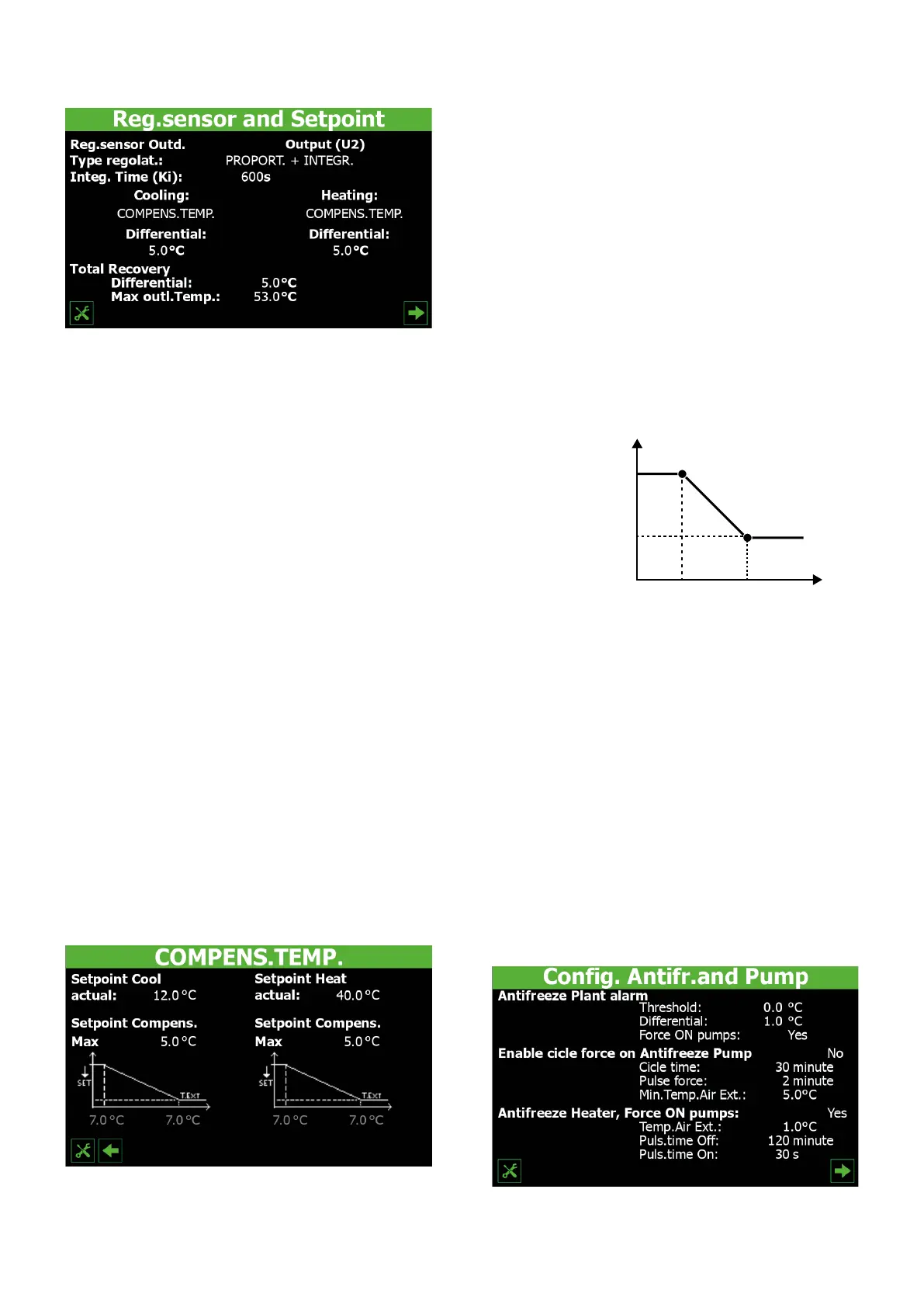
Logic used for calculating the set-point via climate curve
°C
Setpoint (A)
Set-point (A) - Comp.
set-point
External air
External air
1. The set-point (A) indicates the value dened (in both cooling and heating
mode, given that the calculation logic is the same) for normal operation (re-
member that this setting is dened on the rst page of the system menu);
2. The set-point (A) is dened so as to correspond to the minimum outside air
temperature (specied in the relative parameter on the climate curve (cooling/
heating) page;
3. The maximum outside air temperature (specied in the relative parameter on
the climate curve (cooling/heating) page) is associated with the result of the
subtraction of set-point (A) from the compensation set-point (dened on the
climate curve (cooling/heating) page);
4. For outside air temperatures lower than the value indicated as "minimum", the
operating set-point will be equal to the set-point (A);
5. For outside air temperatures between the minimum and maximum indicated,
the set-point will be calculated automatically on the basis of the straight sec-
tion of the climate curve;
6. For outside air temperatures higher than the maximum value, the operating
set-point will be the result of the subtraction of set-point (A) from the com-
pensation set-point;
7.7 CONFIGURING THE ANTIFREEZE CONDITIONS
— Indicates the temperature value for thermostat control (evaporator inlet or out-
let), below which the antifreeze alarm is activated
 Loading...