18
— Indicates the value of the dierential, to be added to the inlet temperature on
the recovery tank (if installed), for quitting the recovery antifreeze alarm con-
dition
— This value is used to choose whether to automatically switch on the pump if the
antifreeze heater is activated (YES = pumps activated together with the heater;
NO = pumps not activated)
— This value is used to choose whether to activate the cyclic pump activation
function on the basis of the outside temperature. This prevents the formation
of ice if the outside temperature falls very low (YES = cyclic pump activation
enabled; NO = cyclic pump activation not enabled)
— Indicates the time gap between two consecutive fan switch-on operations (if
cyclic fan activation is enabled)
— Indicates the duration of the pump cycle (if cyclic pump activation is enabled)
— Indicates the outside air temperature below which cyclic pump activation is
launched (if cyclic pump activation is enabled)
— This value is used to choose whether to activate the cyclic fan activation func-
tion on the basis of the outside temperature. This prevents the accumulation
of snow in the fans, and therefore the risk of ice formation, if the outside tem-
perature falls very low (YES = cyclic fan activation enabled; NO = cyclic fan
activation not enabled)
— Indicates the outside air temperature below which cyclic fan activation is
launched (if cyclic fan activation is enabled)
— Indicates the time gap between two consecutive fan switch-on operations (if
cyclic fan activation is enabled)
— Indicates the duration of the fan cycle (if cyclic fan activation is enabled)
7.8 CONFIGURING THE ANTIFREEZE CONDITIONS AND
THE RECOVERY PUMP IF INSTALLED
— This value is used to choose whether to automatically switch on the pump if the
antifreeze heater is activated (YES = pumps activated together with the heater;
NO = pumps not activated)
— Indicates the number of pumps (only necessary if the pumps are outside the
unit). This value may be 1 or 2
— Indicates the pump inactivity time - i.e. the time in which one of the two pumps
is deactivated while the other is operating. Once this time has elapsed, a pump
rotation operation is performed (to prevent lockout) with automatic compres-
sor switch-o and reactivation. To reduce the cases of forced unit switch-o,
rotation is carried out every time the unit is reactivated after a switch-o (stand-
by), even if the set time has not passed
— Indicates the pump switch-o delay after the deactivation of the compressors
or other sources (heaters, Free-cooling, etc.)
— This value is used to select the logic for managing the recovery pump (if in-
stalled):
NO = the recovery unit is activated when the ow switch contact closes for the
transit of water (the pump is not managed by the unit);
YES = the pump is managed by the unit - it switches o when the water entering
the recovery unit reaches the temperature set-point (remote access to the probe in
the domestic hot water accumulation tank). The pump switches back on when the
temperature of the recovery tank inlet probe falls more than 3°C below the recov-
ery set-point. Apart from the ow switch, the pump thermoswitch (if installed) is
also managed; this triggers the deactivation of the pump and lets you quit recovery
mode.
— Indicates the temperature on the recovery tank inlet (if installed), below which
the antifreeze alarm is activated on the recovery tank
— Indicates the value of the dierential, to be added to the inlet temperature on
the recovery tank (if installed), for quitting the recovery antifreeze alarm con-
dition
7.9 CONFIGURAZIONE DEI VENTILATORI
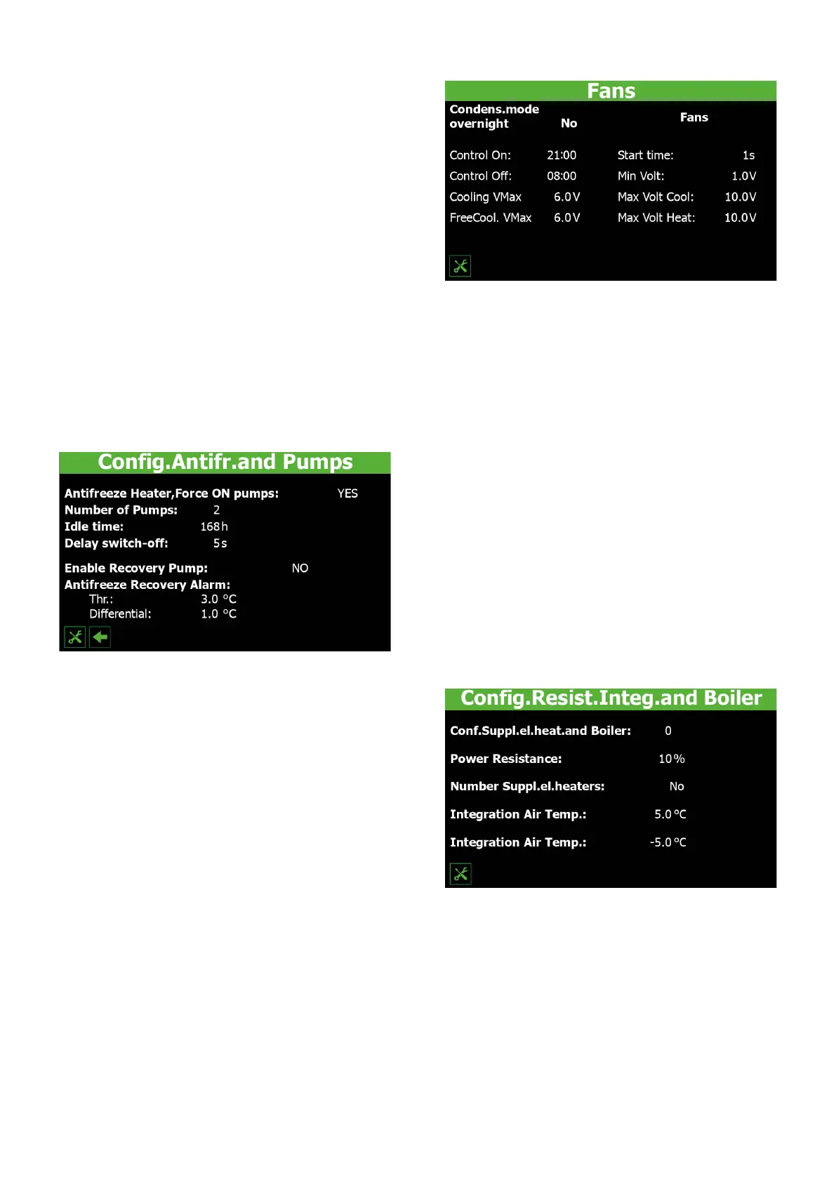
— This value is used to choose whether or not to limit the fan speed during the
specied time band (YES = fans limited according to the specications; NO =
standard fan operation)
— Indicates the start time for the program in which the fans work at reduced
speed (if this function has been activated)
— Indicates the end time for the program in which the fans work at reduced speed
(if this function has been activated)
— Indicates the value (in Volts) for the maximum fan speed (in cooling mode) dur-
ing night-time low noise operation. This value can range from 0 to 10V, with 10V
representing the maximum possible speed
— Indicates the value (in Volts) for the maximum fan speed (in Free-cooling mode)
during night-time low noise operation. This value can range from 0 to 10V, with
10V representing the maximum possible speed
— Indicates the time for which the 4V peak should be maintained at fan start-up
(during normal fan operation)
— Indicates the value (in Volts) for the minimum fan speed during normal opera-
tion. This value can range from 0 to 10V, with 10V representing the maximum
possible speed
— Indicates the value (in Volts) for the maximum fan speed during normal opera-
tion in cooling mode. This value can range from 0 to 10V, with 10V representing
the maximum possible speed
— Indicates the value (in Volts) for the minimum fan speed during normal opera-
tion in heating mode. This value can range from 0 to 10V, with 10V representing
the maximum possible speed
7.10 CONFIGURING THE SUPPLEMENTARY HEATERS AND
REPLACEMENT BOILER IF INSTALLED
— This value indicates the number of supplementary heaters managed by the unit
(via a connection with the pCOe expansion card). This value can range from 0
to 3
— Indicates the power of the minimum step in relation to the unit power (as a
percentage value) (only if the unit is a heat pump)
— This value is used to manage a replacement boiler (on heat pump units only) for
hot water production when the outside air temperature falls below a set limit
(YES = boiler enabled; NO = boiler not enabled)
— Indicates the outside air temperature below which the unit works alongside the
supplementary electric heaters (above this temperature value, the unit works
without the heaters)
— Indicates the outside air temperature below which the unit is completely re-
placed (it goes into standby) by the supplementary heaters or (if congured)
the boiler for hot water production
 Loading...