19
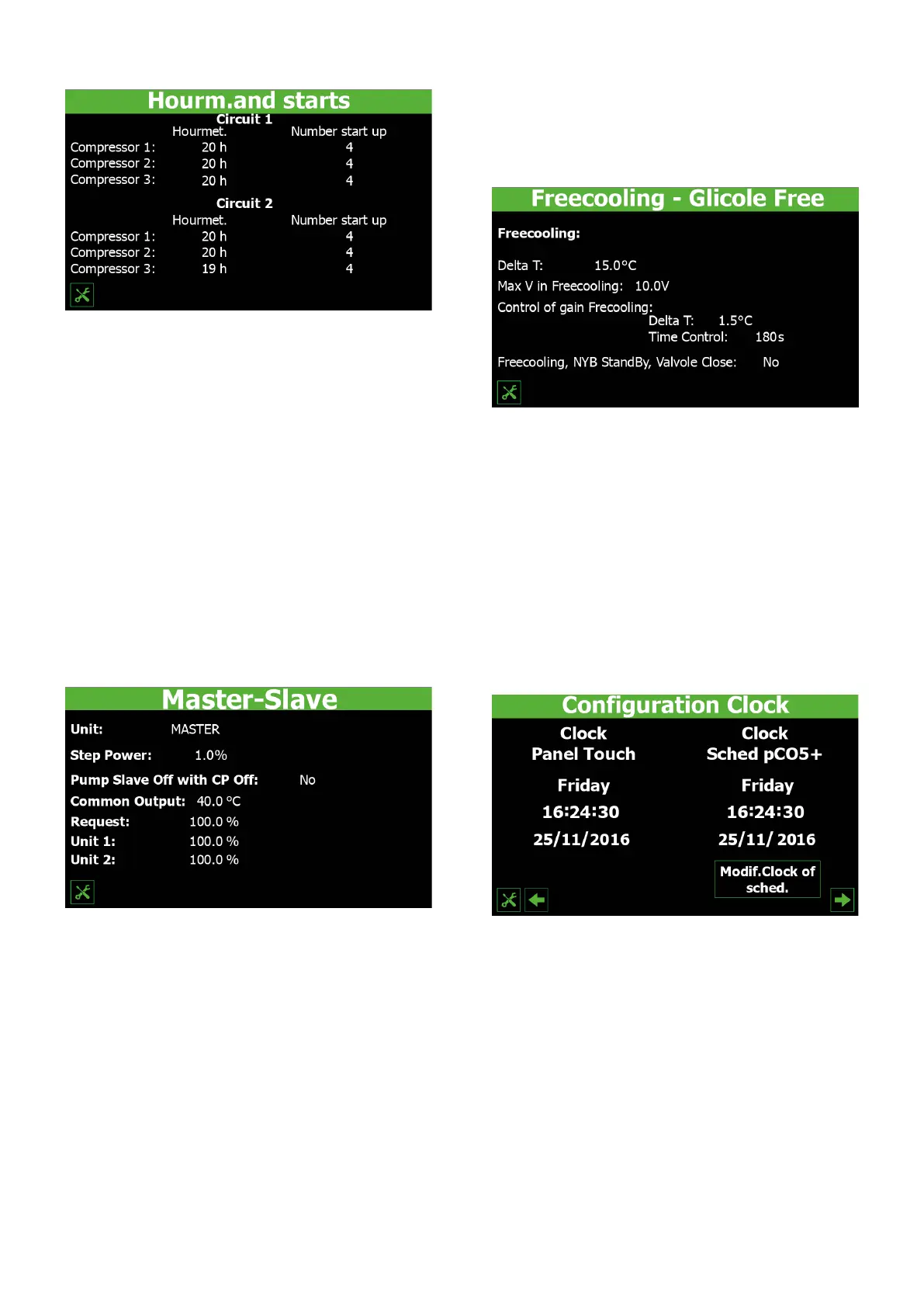
7.11 COMPRESSOR OPERATING LOG
— Indicates the number of hours that compressor 1 on circuit 1 has worked
— Indicates the number of hours that compressor 2 on circuit 1 (if installed) has
worked
— Indicates the number of hours that compressor 3 on circuit 1 (if installed) has
worked
— Indicates the number of peaks made by compressor 1 on circuit 1
— Indicates the number of peaks made by compressor 2 on circuit 1 (if installed)
— Indicates the number of peaks made by compressor 3 on circuit 1 (if installed)
— Indicates the number of hours that compressor 1 on circuit 2 (if installed) has
worked
— Indicates the number of hours that compressor 2 on circuit 2 (if installed) has
worked
— Indicates the number of hours that compressor 3 on circuit 2 (if installed) has
worked
— Indicates the number of peaks made by compressor 1 on circuit 2 (if installed)
— Indicates the number of peaks made by compressor 2 on circuit 2 (if installed)
— Indicates the number of peaks made by compressor 3 on circuit 2 (if installed)
7.12 MASTER SLAVE CONFIGURING POWER CONTROL IN
THE CASE OF TWOUNIT SYSTEMS
This window is used to congure the parameters for unit Master/Slave manage-
ment:
1. Used to choose whether the unit is part of a Master/Slave system. The possible
values are:
SINGLE = the unit is single so no connection is activated and there is no Master/
Slave control;
MASTER = the unit is part of a two-unit system (and connected via pLAN). The cur-
rent setting indicates that the unit is the Master;
SLAVE = the unit is part of a two-unit system (and connected via pLAN). The current
setting indicates that the unit is a Slave;
2. Indicates the percentage of the system power request that will be divided be-
tween the Master and the Slave. This value can range from 1 to 100%, with 1%
indicating that the two units will work in parallel and 100% indicating that the
units will be used in a sequential manner (the power of the Slave will only be
used when all the Master power has been used)
3. Choose whether to activate the Slave pump only if the Slave unit is involved
in the power request, or activate it whenever a request is received from the
system (YES = Slave pump disabled if there is no request on the Slave unit; NO
= Slave pump always enabled in response to a request)
4. Indicates the temperature measured on the common outlet of the Master and
Slave units
5. Indicates the power value currently requested by the system (as a percentage)
6. Indicates the power value currently supplied by the Master in response to a
request from the system (as a percentage)
7. Indicates the power value currently supplied by the Slave in response to a re-
quest from the system (as a percentage)
7.13 CONFIGURING THE FREECOOLING UNIT IF
INSTALLED
— Indicates the temperature dierence (in Free-cooling) generated at the maxi-
mum fan speed
— Indicates the value (in Volts) assigned to the fans during Free-cooling. This value
can range from 0 to 10V
— Indicates the value to be assigned to the temperature dierence at the max-
imum fan speed during Free-cooling. This parameter is part of the constant
check that the Free-cooling coil produces a T-delta (used as a safety check on
3-way valve operation)
— Indicates the bypass time from Free-cooling start-up before beginning the
Free-cooling output check
— This value is used to manage the logic of the valves on the NYB. This may be:
YES = no transit of water during unit standby;
NO = transit of water in the evaporator during unit standby;
7.14 CONFIGURING THE CTOUCH CLOCK AND THE PCO5
CLOCK
— Indicates the current day of the week on the C-Touch timer
— Indicates the current time on the C-Touch timer
— Indicates the current date on the C-Touch timer
— Indicates the current day of the week on the pCO5 timer
— Indicates the current time on the pCO5 timer
— Indicates the current date on the pCO5 timer
 Loading...