12
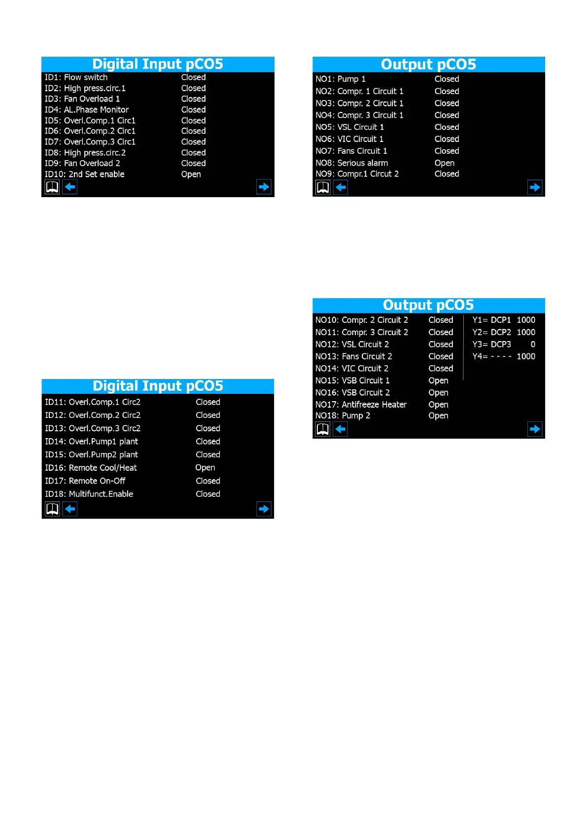
4.7 PCO5 DIGITAL INPUT STATUS
1. Indicates the status of the evaporator ow switch
2. Indicates the status of the high-pressure switch for circuit 1
3. Indicates the status of the thermal protection on fan 1
4. Indicates the status of the phase monitor
5. Indicates the status of the thermal protection on compressor 1 (circuit 1)
6. Indicates the status of the thermal protection on compressor 2 (circuit 1)
7. Indicates the status of the thermal protection on compressor 3 (circuit 1)
8. Indicates the status of the high-pressure switch for circuit 2
9. Indicates the status of the thermal protection on fan 2
10. Indicates the setting for the second set-point
Closed = normal operation; Open = fault in progress;
11. Indicates the status of the thermal protection on compressor 1 (circuit 2 if
installed)
12. Indicates the status of the thermal protection on compressor 2 (circuit 2 if
installed)
13. Indicates the status of the thermal protection on compressor 3 (circuit 2) (if
installed)
14. Indicates the status of the thermal protection on evaporator pump 1
15. Indicates the status of the thermal protection on evaporator pump 2
Closed = normal operation; Open = fault in progress;
16. Indicates the setting for the remote season changeover command
17. Indicates the setting for the remote ON/OFF command
18. Indicates the setting for the multi-purpose input
Closed = input enabled; Open = input not enabled;
4.8 PCO5 DIGITAL OUTPUT STATUS
1. Indicates the status of pump 1
2. Indicates the status of compressor 1 (circuit 1)
3. Indicates the status of compressor 2 (circuit 1)
4. Indicates the status of compressor 3 (circuit 1)
5. Indicates the status of the liquid solenoid valve (circuit 1)
6. Indicates the status of the reverse cycle valve (circuit 1)
7. Indicates the status of the fans on circuit 1
8. Indicates the status of the "serious alarm" signal
9. Indicates the status of compressor 1 (circuit 2)
10. Indicates the status of compressor 2 (circuit 2)
11. Indicates the status of compressor 3 (circuit 2)
12. Indicates the status of the liquid solenoid valve (circuit 2)
13. Indicates the status of the fans on circuit 2
14. Indicates the status of the reverse cycle valve (circuit 2)
15. Indicates the status of the thermostat bypass solenoid valve (circuit 1)
16. Indicates the status of the thermostat bypass solenoid valve (circuit 2)
17. Indicates the status of the antifreeze heater:
18. Indicates the status of pump 2
Closed = load operating; Open = load not operating;
19. Indicates the voltage value applied to the DCP1 modulating fan unit (from 0
to 10,00V)
20. Indicates the voltage value applied to the DCP2 modulating fan unit (from 0
to 10,00V)
21. Indicates the voltage value applied to the DCP3 (or DCP1+DCP2) modulating
fan unit (from 0 to 10,00V)
22. Indicates the voltage value applied to the modulating fan unit of circuit 1 that
switches o in the event of low outside temperatures
 Loading...