8
3 MAIN PAGE HOME
The standard display during normal operation is the "Home" page. Depending on
the type of unit congured, from this window you can keep the main operating
parameters under control or access direct connections to certain operating menus.
We will analyse and explain below all the elements that can be viewed and/or man-
aged via the Home page.
ATTENTION: certain information is only visible if it is available on the unit
(for example data relating to the Free-cooling circuit).
3.1 DATA ENTERED IN THE UPPER BAR
— Date set on the system
— String corresponding to the unit congurator (for more information about the
unit congurator, refer to the technical manual of the unit itself).
— Time set on the system
Note:
The units have two dierent timers - one integrated in the C-touch panel and the
other relating to the electric control card of the units. These timers can have dif-
ferent time settings (which can be seen on the "Clock conguration" page of the
installer menu), to ensure the correct time is shown for any alarms saved in the log.
You are advised to check them regularly to make sure they coincide, synchronising
them if necessary.
The congured unit code is entered in the factory, and cannot be altered by the
user.
3.2 WATER INLET/OUTLET TEMPERATURE CHART
The chart on the homepage shows the temperature trend of the water entering and
leaving the unit. The colours will depend on the unit operating mode: in cooling
mode, BLUE indicates the outlet water and RED the inlet water; on the contrary,
in heating mode RED indicates the processed water and BLUE the water returning
from the system.
Click on the chart to directly open the "chart menu", where you can see a log of the
various charts available. To return to the main page, you must rst go to the menu
selection page and from there select "Home".
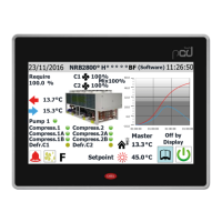
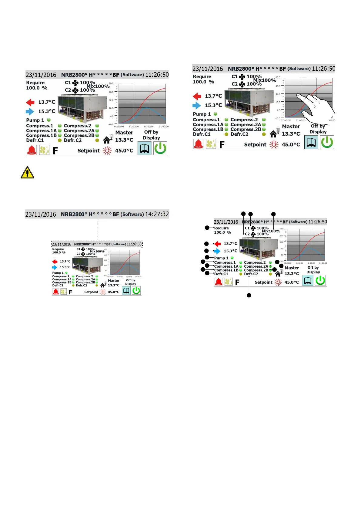
3.3 UNIT OPERATING STATUS INFORMATION REAL TIME
DATA
7
1
2
3
4
5
6
8
2
9
10
11
12
13
14
15
1. Percentage gure showing the power request from the system
2. Percentage gure showing the speed of the fans on circuit 1
3. Percentage gure showing the speed of the fans on circuit 2 (only visible if the
unit has 2 circuits)
4. Percentage gure showing the speed of the shared fans in V-BLOCK units (only
visible on V-BLOCK units)
5. Indicates the temperature of the water processed by the unit (real time gure)
6. Indicates the temperature of the water entering the unit (real time gure)
7. This label appears if the unit pump is active (if the unit has a pump component)
8. This label appears if unit compressor 1 is active
9. This label appears if unit compressor 1A is active (if installed)
10. This label appears if unit compressor 1B is active (if installed)
11. This label appears if defrosting is in progress on circuit 1
12. This label appears if unit compressor 2 is active (if installed)
13. This label appears if unit compressor 2A is active (if installed)
14. This label appears if unit compressor 2B is active (if installed)
15. This label appears if defrosting is in progress on circuit 2 (on two-circuit units
only)
Note: Much of the information in this section is linked to the type of unit: the pres-
ence of a second circuit or a hydronic side pump, or the number of compressors
managed by the system, will depend on the type of unit.
 Loading...