16
7 INSTALLER MENU
The INSTALLER menu is used to access many of the settings for operating and ad-
justing the unit; it may, however, contain parameters that should only be modied
by persons responsible for maintenance and/or assistance on the unit or system,
and for this reason it's protected by a password.
USER PASSWORD: 0000
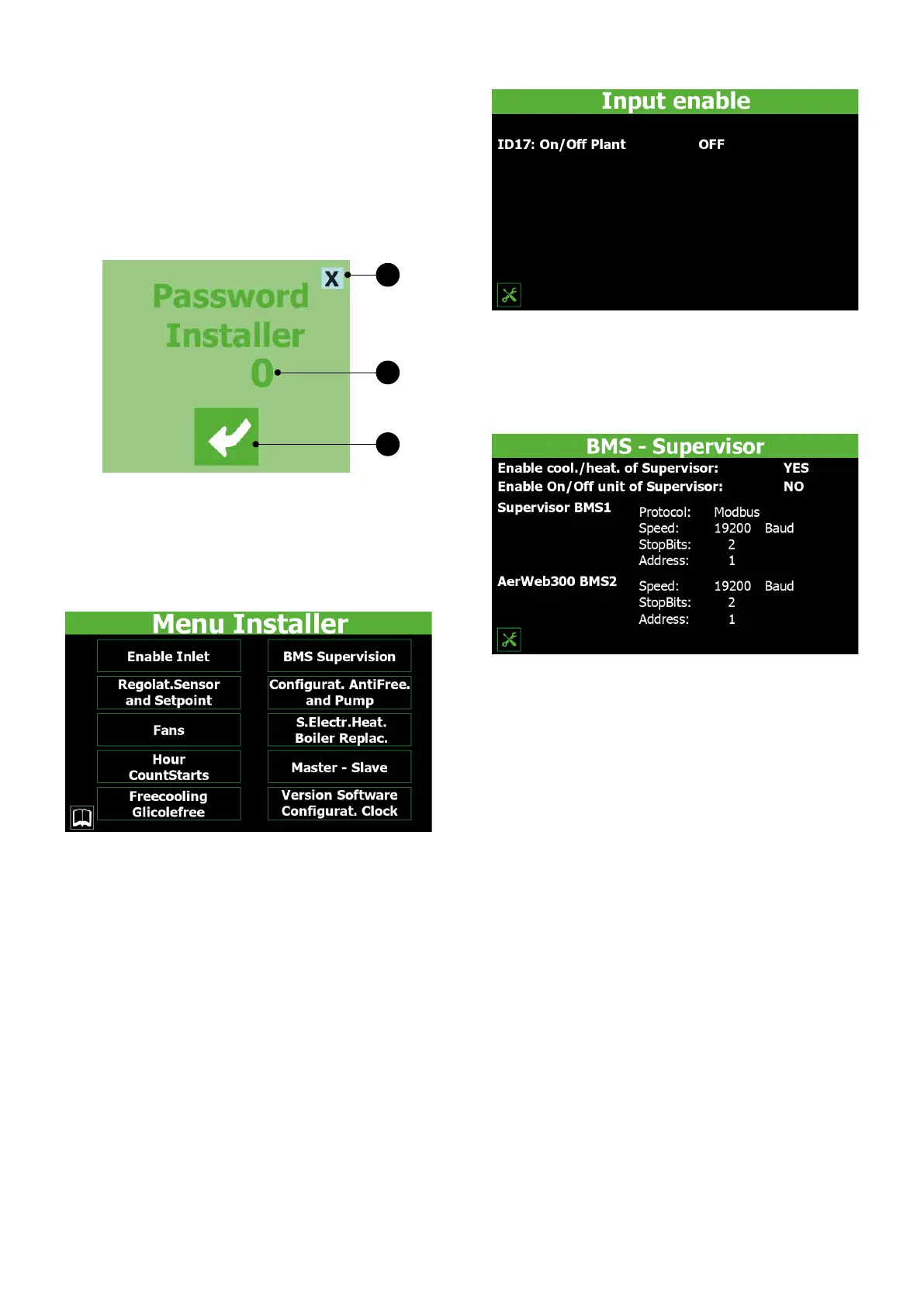
7.1 ENTERING THE PASSWORD FOR ACCESSING THE
PROTECTED MENU
1
2
3
1. This key is used to quit the window and go back to the menu selection page
2. Indicates the current value of the password to be used for accessing the in-
staller menu
3. This key is used to conrm the access password entered
7.2 SELECTING THE SUBMENUS
1. Input Enable:
This key is used to access the "Input enabling" sub-menu
2. Probe Regulation:
This key is used to access the "Probe adjustment and set-point" sub-menu
3. Fans:
This key is used to access the "Fans" sub-menu
4. Hour counters:
This key is used to access the "Hour-counter and Peak-counter" sub-menu
5. Freecooling - Glycol Free:
This key is used to access the "Free-cooling (glycol-free)" sub-menu
6. BMS Supervision:
This key is used to access the "BMS supervision" sub-menu
7. Antifreeze Conguration:
This key is used to access the "Antifreeze and pump conguration" sub-menu
8. Supplementary heaters/replacement boiler:
This key is used to access the "Supplementary heaters and replacement boiler" sub-
menu
9. Master - Slave:
This key is used to access the "Master-Slave" sub-menu
10. Software version/clock conguration:
This key is used to access the "Software version and clock conguration" sub-menu
7.3 ENABLING ON/OFF VIA DIGITAL INPUT ID17
Indicates the current setting for the "On/O via digital input ID17" function (YES =
function enabled; NO = function disabled)
7.4 ENABLING AND SETTING CONTROL VIA THE REMOTE
SUPERVISOR BMS
— Indicates the current setting for changeover via the supervisor (YES = function
enabled; NO = function disabled)
— Indicates the current setting for ON/OFF via the supervisor (YES = function ena-
bled; NO = function disabled)
— May indicate the current protocol selected for communication between the unit
and BMS. The protocols available are:
Modbus = RS485 modbus supervisor;
Carel = communication protocol for controlling the expansion cards;
pCOWeb = communication protocol for the pCOWeb expansion card;
Lon = communication protocol for controlling the Lon expansion cards;
Modbus Ext = extended modbus communication protocol (if you select this pro-
tocol, you will have the same addresses available on BMS2 for AERNET or another
supervisor);
— Indicates the current communication speed between the unit and the supervi-
sion system BMS1. The values that can be set are: 1200, 19200 or 38400 Baud
— Indicates the current number of stop bits for communication between the unit
and the supervision system BMS1. The values that can be set are: 1 or 2
— Indicates the current address assigned to the unit for communicating with the
remote supervisor BMS1
— Indicates the current communication speed between the unit and the supervi-
sion system BMS2. The values that can be set are: 1200, 19200 or 38400 Baud
— Indicates the current number of stop bits for communication between the unit
and the supervision system BMS2. The values that can be set are: 1 or 2
— Indicates the current address assigned to the unit for communicating with the
remote supervisor BMS2
 Loading...