Chapter 5: Troubleshooting
Power Board Trouble Isolation
5–24
Power Board Trouble Isolation
Power Board Check
Connector Test Point Specification Range
J4 AVDD4F
AVDD34
+1.62 V ± 1%
+1.60 V ± 3%
+1.60 V to +1.64 V
+1.55 V to +1.65 V
J5 AVDD3F
+2.0 V
-1.4 V
+1.62 V ± 1%
+2.0 V ± 0.4%
-1.4 V ± 0.3%
+1.60 V to +1.64 V
+1.992 V to +2.008 V
-1.3958 to -1.4042 V
J6 +3.3 V
-5.2 V
+3.35 V ± 0.4%
-5.2 V ± 0.4%
+3.3366 V to +3.3634 V
-5.1792 V to -5.2208 V
J7 + 5VF
-2 V
-3.3 V
AVDD2F
+5.0 V ± 0.4%
-2.0 V ± 0.4%
-3.3 V ± 0.4%
+1.62 V ± 1%
+4.98 V to +5.02 V
-1.992 V to -2.008 V
-3.2868 V to -3.3132 V
+1.6038 V to +1.6362 V
J8 AVDD12
AVDD1F
+1.60 V ± 3%
+1.62 V ± 1%
+1.552 V to +1.648 V
+1.6038 V to +1.6362 V
J9 +2.5 V
-12 VF
+12 VF
+2.5 V ± 0.4%
-12 V± 10%
+12 V ± 0.4%
2.49 V to +2.51
-10.8 V to -13.2 V
+11.952 V to +12.048 V
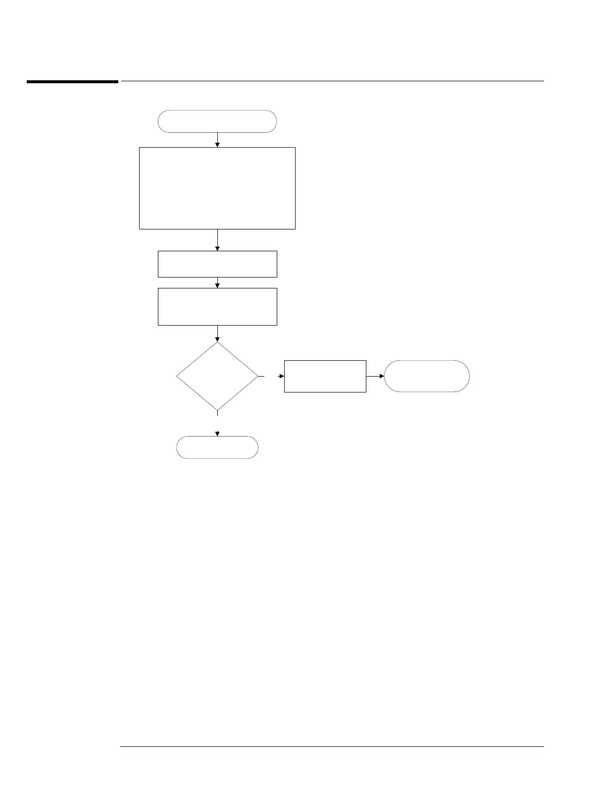
Power Board Verification
Ensure unit is configured as follows:
Power supply connected to power
board. Acquisition board removed.
Probe interface board, A9,
disconnected from the power board.
Connect ac power.
Verify voltages on power
board.
Are
voltages within
spec?
Replace power
board.
No
Go to ’Primary
Trouble Isolation’.
Power board OK.
Yes
 Loading...


