Chapter 6: Replacing Assemblies
To remove and replace the front panel assembly
6–13
To remove and replace the front panel assembly
When necessary, refer to other removal procedures.
1 Disconnect the power cable and remove the top and bottom covers.
2 Remove the Auto-Probe assembly A16 and Mylar flex cable W8.
3 Using a 5/8” nut driver, remove the hex nuts that secure the BNC connectors to the front
panel.
Figure 5-12
Removing the BNC Nuts
4 Remove the power supply spring cover from the left side of the chassis.
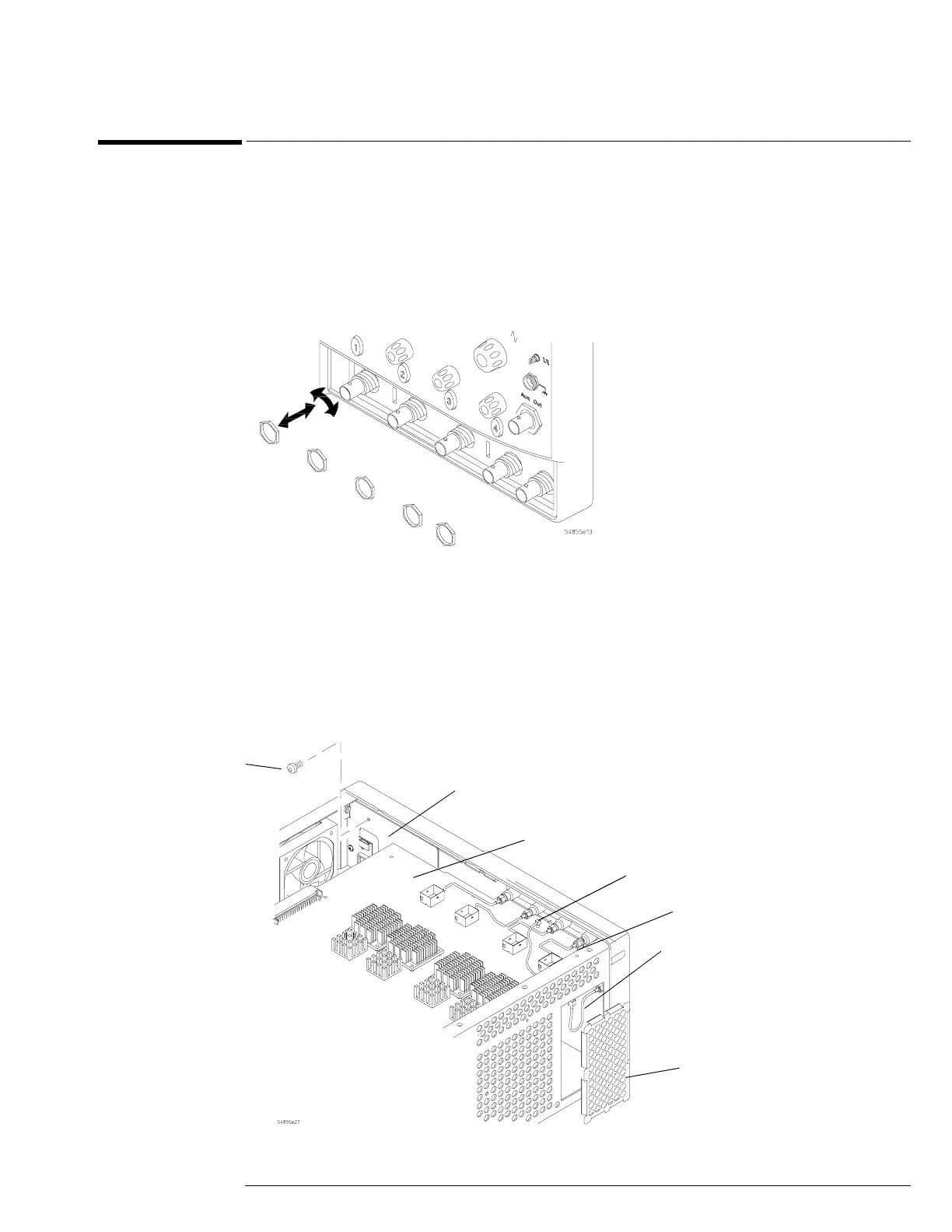
5 Using a 5/16” open-end wrench, disconnect the Aux Out semi-rigid cable from the rear of
the front panel.
6 Disconnect the probe comp wire from the acquisition board. If necessary, use pliers to
remove the probe comp wire.
7 Remove the Torx T10 screw that secures the front frame to the chassis.
Figure 5-13
Removing Aux Out Cable W9, Probe Comp Wire W10, and Back Plate Screw
Torx
T10
Front frame back plate
Acquisition board
Probe comp wire
Aux Out cable
Power supply
spring cover
Aux Trig In SMB Cable
 Loading...


