Chapter 3: Testing Performance
Internal Channel Trigger Sensitivity Test
3–32
Internal Channel Trigger Sensitivity Test
Specification
Equipment Required
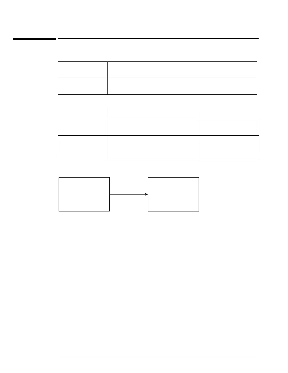
Connections
Procedure
Low Sensitivity Measurements @ 2 GHz
1
Connect the microwave signal source to scope channel 1 as shown in the connection
diagram above.
2 Set up the scope as follows:
a Press Default Setup.
b Set channel 1 vertical sensitivity to 1.0 V/div.
c Set the horizontal scale to 2 ns/div.
Low sensitivity mode: 54855A: 0.5 div p-p 0 to 2 GHz, 1.0 div p-p 2 to 4 GHz, <2.5 div @ 5 GHz
54854A: 0.5 div p-p 0 to 2 GHz, 1.0 div p-p 2 to 4 GHz
54853A: 0.5 div p-p 0 to 2 GHz, 1.0 div p-p 2 to 2.5 GHz
High sensitivity mode: 54855A: 0.2 div p-p 0 to 6 GHz
54855A: 0.2 div p-p 0 to 4 GHz
54855A: 0.2 div p-p 0 to 2.5 GHz
Description Critical Specifications Recommended Model/
Part Numbers
Microwave CW Generator Maximum Frequency ≥6 GHz
Power range: -20 dBm to +16 dBm into 50Ω
Output resistance = 50Ω
Agilent E8247C with Opt 520 or
Agilent 82712B with Opt 1E5 or
Agilent 8665B with Opt 004
Microwave Cable Assembly 50Ω Characteristic Impedance
3.5 mm (m) or SMA (m) connectors
Max Frequency ≥18 GHz
Agilent 8120-4948 or
Agilent 11500E or
Gore EKD01D010480
Adapters 3.5 mm (f) to Precision BNC Agilent 54855-67604
Scope
Under
Test
Channel 1
Microwave
Signal
Source
50 Ohm
RF Output
 Loading...


