SUM Subsystem Introduction
OUTPut1 1
OUTPut2 1
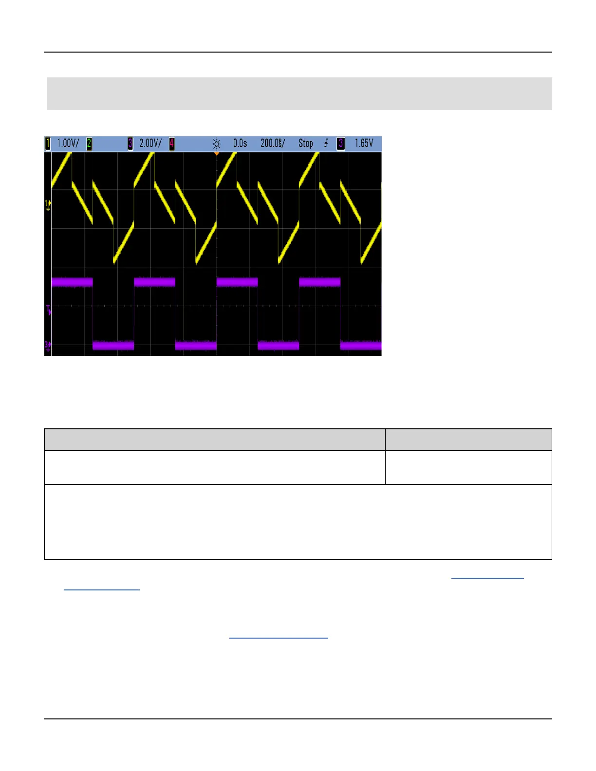
This oscilloscope image produced by this code is shown below.
[SOURce[1|2]:]SUM:AMPLitude <amplitude>
[SOURce[1|2]:]SUM:AMPLitude? [{MINimum|MAXimum}]
Sets internal modulation depth (or "percent modulation") in percent.
Parameter Typical Return
Desired SUM signal amplitude in percent of carrier amplitude, from 0 to 100;
default 0.1
+3.200000000000000E+00
Set the internal SUM signal amplitude to 1.0% of the signal amplitude:
SUM:AMPL 1.0
PHAS:SYNC
Set the internal sum signal amplitude on channel 2 to 0.15% of the signal amplitude:
SOUR2:SUM:AMPL 0.15
l You can synchronize the phase between the primary signal and the SUM signal by sending SOURce[1|2]:PH-
ASe:SYNChronize after setting the functions for the primary signal and the SUM signal. Otherwise, the phase
between the two signals is arbitrary.
l Summed output cannot exceed ±5 V peak output (into a 50 Ω load).
l If you select the External SUM source (SUM:SOURce EXTernal), the carrier waveform is added to the external
waveform. The summing signal is the ±5 V signal level on the rear-panel Modulation In connector. For example,
if you have the carrier amplitude of a sine wave set to 4 Vpp and set the Sum Amplitude to 20% (resulting in a
maximum sum contribution of 800 mVpp) using SUM:AMPLitude, then when the EXT signal is at +5 V, the addi-
tive signal output will be at the maximum amplitude of 4.8 Vpp. When the modulating signal is at -5 V, the additive
292 Agilent 33500 Series Operating and Service Guide

 Loading...


