Output Impedance Adjustment (Channel 2)
Output Impedance Adjustment (Channel 2)
The instrument stores calibration constants for the channels' output impedance. These constants are generated with
and without the post-amplifier attenuator.
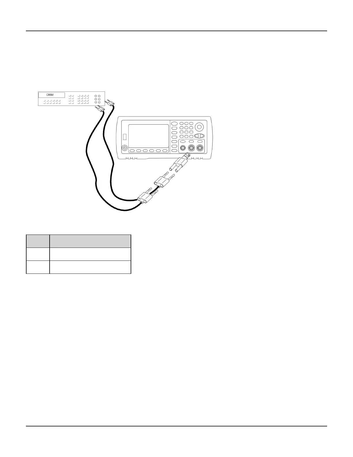
1. Set the DMM to measure offset-compensated, four-wire Ohms. Set the DMM to use 100 NPLC integration. Con-
nect the Ohms Source and Ohms Sense DMM inputs to the channel output as shown below.
2. Use the DMM to make a 4-wire resistance measurement at the front panel output connector for each setup in the
following table. The expected measured value is approximately 50 Ω.
Setup
55* -24 dB post-attenuator range
56* 0 dB range
* Constants are stored after completing this setup.
3. Using the numeric keypad or knob, adjust the displayed impedance at each setup to match the measured imped-
ance. Select ENTER VALUE.
4. There are no specific operational verification tests for output impedance. Continue with the next adjustment pro-
cedure in this section.
400 Agilent 33500 Series Operating and Service Guide

 Loading...


