28 Rockwell Automation Publication 8720MC-RM001K-EN-P - September 2018
Chapter 4 Connector Data and Feature Descriptions
8720MC Regenerative Power
Supply Connector Data
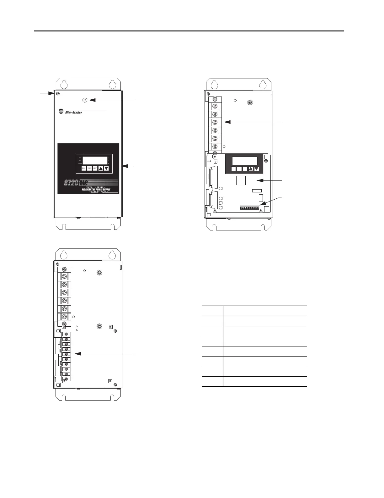
Use these illustrations to identify the terminal blocks and other features of the
8720MC-RPS units.
Figure 8 - 8720MC-RPS065 Unit
For access to the terminal blocks and regulator board:
• Remove the cover screw (item 7) to remove the front cover.
• The regulator board has two ribbon cables on the left side and two
screws on the right side. Remove the two screws and the board swings
open, hinged by the ribbon cables.
RST PRG ENT
READY
FAULT
PROGRAM
A
V
kW
3
4
5
8720MC-RPS065
8720MC Regenerative Power Supply
(with front cover removed)
Item Description
1 Operation panel (leader unit only)
2Power status indicator
3 Main power (TB1) terminal block
4 Regulator board (leader unit only)
5 Sequence signal (TB3) terminal block
6 Control power (TB2) terminal block
7 Hole for Cover Fixing Screw
8720MC-RPS065
8720MC Regenerative Power Supply
(with front cover and
regulator board removed)
8720MC-RPS065
8720MC Regenerative Power Supply
(with front cover)
 Loading...


