68 Rockwell Automation Publication 8720MC-RM001K-EN-P - September 2018
Chapter 5 Connect the 8720MC-RPS Unit
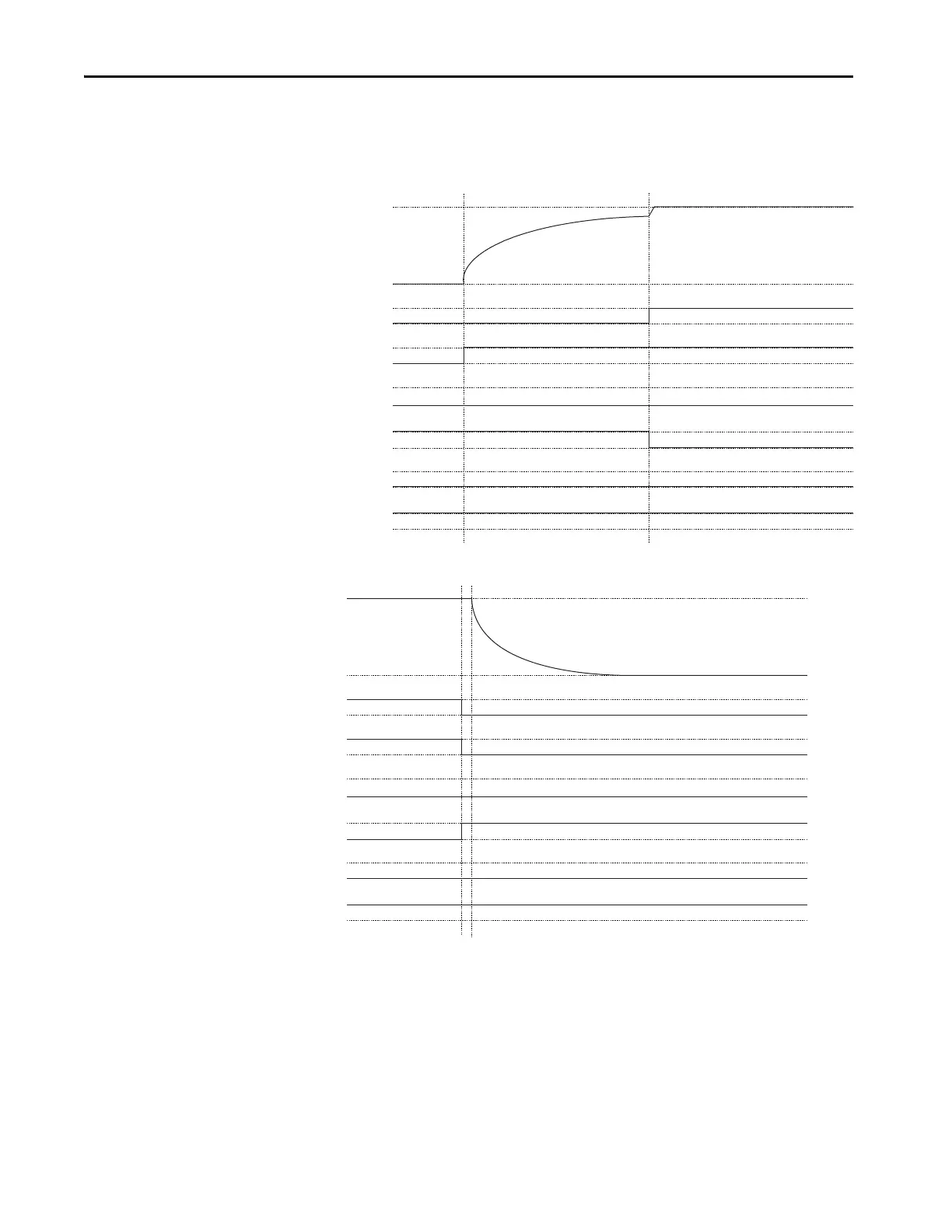
Operation Timing of
Sequence Control Signals
The following timing diagrams describe the sequence of operations for
precharge, discharge, error detection, error resetting, and power loss.
Figure 33 - Sequence Operation of Precharging
Figure 34 - Sequence Operation of Discharging
PWR Input
RST Input
RDY Output
FR Output
IP Output
On
O
On
O
Open
Close
Open
Close
Open
DC Bus Voltage
Main Magnetic
Contactor (MC)
On
O
Close
DC Bus Voltage
Main Magnetic
Contactor (MC)
PWR Input
RST Input
RDY Output
FR Output
IP Output
On
O
On
O
On
O
Open
Close
Open
Close
Open
Close
 Loading...


