Publication 1763-UM001E-EN-P - June 2015
122 Using the LCD
Using the Mode Switch
The MicroLogix 1100 provides the controller mode switch on the LCD. The
possible positions of the mode switch are PROGRAM, REMOTE, and RUN.
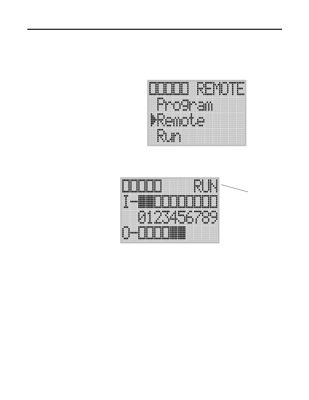
You can change mode switch position using the Mode Switch screen on the
LCD, as shown below. In this example, the mode switch position is set to
REMOTE.
All the built-in LCD screens except the Boot Message screen display the current
mode switch position, at their top right portion, as shown below. In this example,
the mode switch position is set to RUN.
Controller Modes
The table below shows the possible controller modes when the mode switch
positions at PROGRAM, REMOTE, or RUN. For example, if the Mode
Switch is at RUN and you want to test a control program with running it for a
single scan, you have to first change mode switch position to REMOTE
before you run the control program in the remote test single scan mode with
your RSLogix 500 programming software.
Current Mode Switch Position

 Loading...


