Publication 1763-UM001E-EN-P - June 2015
Troubleshooting Your System 187
I/O Status Indicators on the LCD
I/O Status Indicators on the LCD
BAT. LO off
(empty rectangle)
Batterty level is acceptable
on
(solid rectangle)
Battery low
U-MSG off
(empty rectangle)
Default display mode
on
(solid rectangle)
Customized display mode
(1)
When using a MicroLogix 1100 controller, the DCOMM LED applies only to Channel 0.
I/O Status Indicators on the LCD
Indicator Color Indicates
INPUTS
(1)
(1)
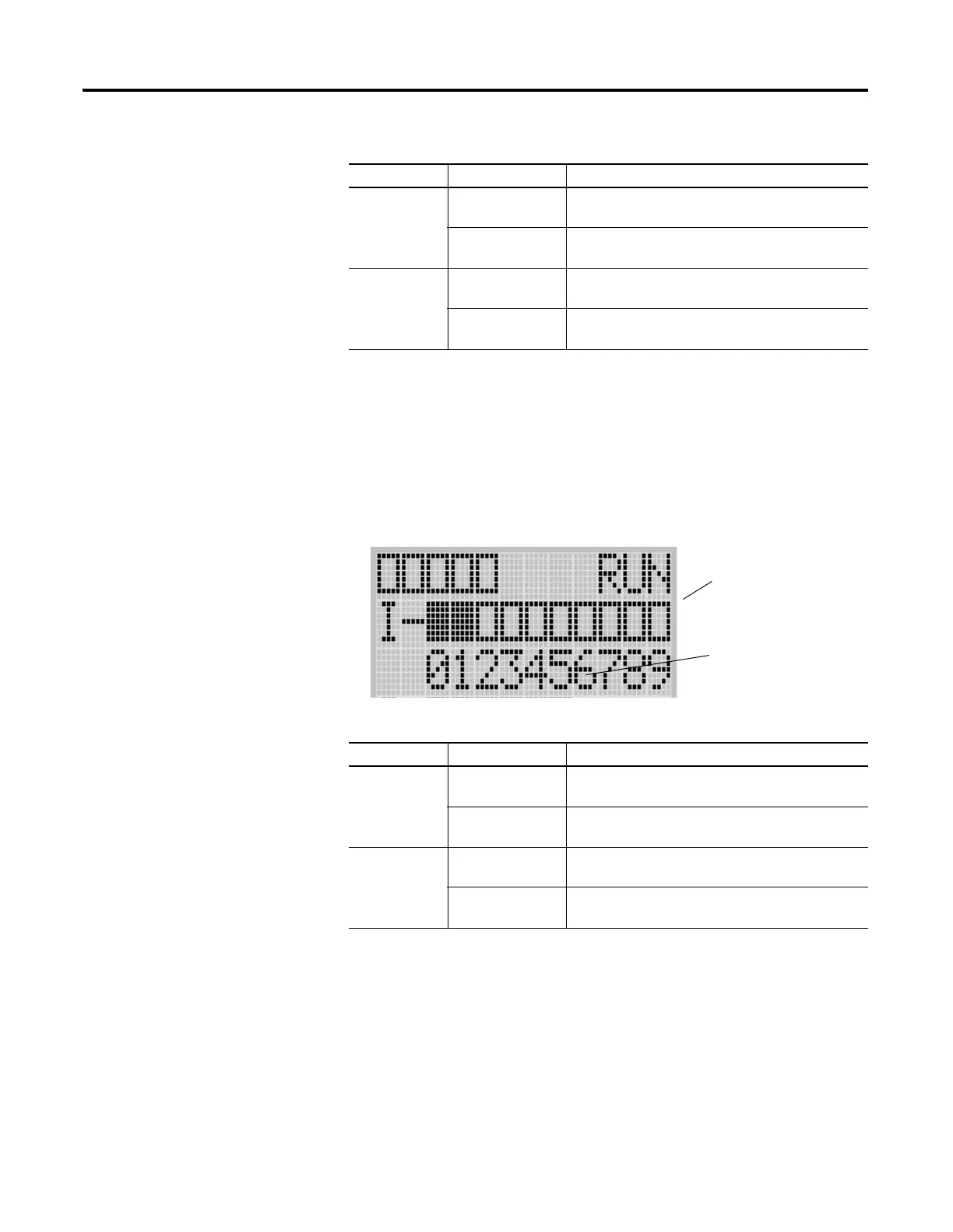
To view the status of inputs and outputs on the LCD, you need to enter the I/O LED mode screen using the LCD
menu. See I/O Status on page 5-107 for more information.
off
(empty rectangle)
Input is not energized
on
(solid rectangle)
Input is energized (terminal status)
OUTPUTS off
(empty rectangle)
Output is not energized
on
(solid rectangle)
Output is engerized (logic status)
Status Indicators on the LCD
Indicator Color Indicates
Output status indicators (6)
Input status indicators (10)
I/O LED screen on the LCD

 Loading...


