Publication 1763-UM001E-EN-P - June 2015
Communication Connections 95
Powering the AIC+
MicroLogix 100, 1200, and 1500 programmable controllers support 24V DC
communication power on Channel 0. When connected to the 8 pin mini-DIN
connector on the 1761-NET-AIC, 1761-NET-ENI, and the
1761-NET-ENIW, these controllers provide the power for the interface
converter modules. The MicroLogix 1100 does not provide 24V DC
communication power. Instead these pins are used to provide RS-485
communications directly. Any AIC+, ENI, or ENIW not connected to a
MicroLogix 1000, 1200, or 1500 controller requires a 24V DC power supply.
If both the controller and external power are connected to the AIC+, the
power selection switch determines what device powers the AIC+.
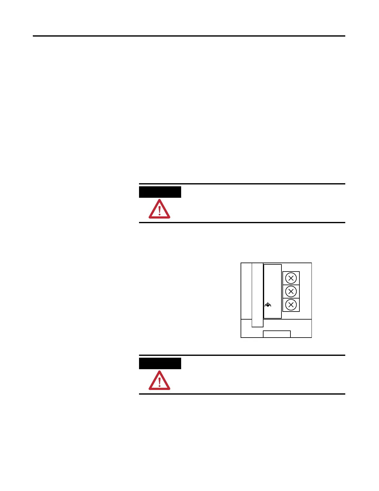
Set the DC Power Source selector switch to EXTERNAL before connecting
the power supply to the AIC+. The following illustration shows where to
connect external power for the AIC+.
If you use an external power supply, it must be
24V DC (-15%/+20%). Permanent damage results if a
higher voltage supply is used.
Always connect the CHS GND (chassis ground)
terminal to the nearest earth ground. This connection
must be made whether or not an external 24V DC supply is
used.
24V DC
DC
NEUT
CHS
GND
Bottom View

 Loading...


