Publication 1763-UM001E-EN-P - June 2015
Wiring Your Controller 49
Terminal Groupings
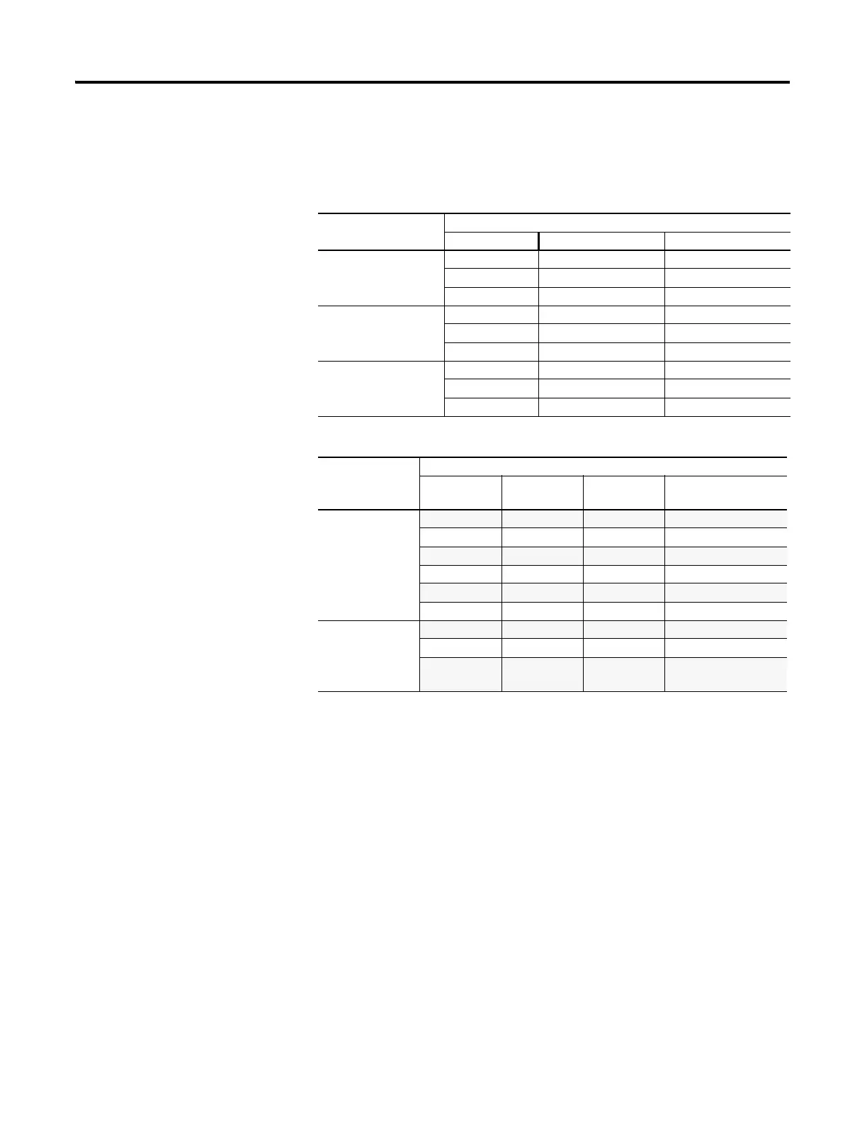
Input Terminal Grouping
Controller Inputs
Input Group Common Terminal Input Terminal
1763-L16AWA
Group 0 AC COM 0 I/0 through I/3
Group 1 AC COM 1 I/4 through I/9
Group 2 IA COM IV1(+) and IV2(+)
1763-L16BWA
Group 0 DC COM 0 I/0 through I/3
Group 1 DC COM 1 I/4 through I/9
Group 2 IA COM IV1(+) and IV2(+)
1763-L16BBB
1763-L16DWD
Group 0 DC COM 0 I/0 through I/3
Group 1 DC COM 1 I/4 through I/9
Group 2 IA COM IV1(+) and IV2(+)
Output Terminal Grouping
Controller Outputs
Output
Group
Voltage
Terminal
Output
Terminal
Description
1763-L16AWA
1763-L16BWA
1763-L16DWD
Group 0 VAC/VDC O/0 Isolated Relay output
Group 1 VAC/VDC O/1 Isolated Relay output
Group 2 VAC/VDC O/2 Isolated Relay output
Group 3 VAC/VDC O/3 Isolated Relay output
Group 4 VAC/VDC O/4 Isolated Relay output
Group 5 VAC/VDC O/5 Isolated Relay output
1763-L16BBB
Group 0 VAC/VDC O/0 Isolated Relay output
Group 1 VAC/VDC O/1 Isolated Relay output
Group 2 DC +24V,
DC -24V
O/2 through
O/5
FET output

 Loading...


