EasyManuals Logo
Home>Allen-Bradley>Controller>MicroLogix 1100

Allen-Bradley MicroLogix 1100 User Manual

Allen-Bradley MicroLogix 1100
256 pages
To Next Page IconTo Next Page
To Previous Page IconTo Previous Page
Page #35 background imageLoading...
Page #35 background image
Publication 1763-UM001E-EN-P - June 2015
Installing Your Controller 33
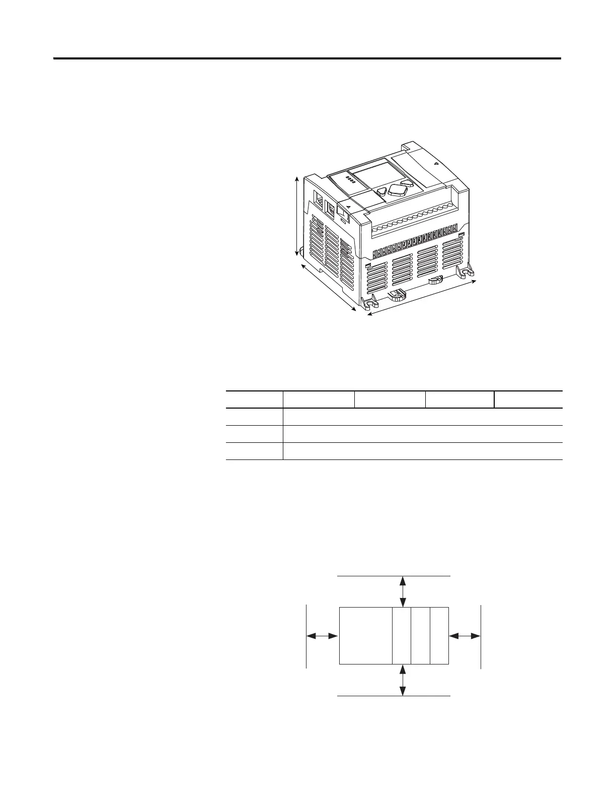
Controller Mounting
Dimensions
Controller and Expansion
I/O Spacing
The controller mounts horizontally, with the expansion I/O extending to the
right of the controller. Allow 50 mm (2 in.) of space on all sides of the
controller system for adequate ventilation. Maintain spacing from enclosure
walls, wireways, adjacent equipment, etc., as shown below.
C
B
A
1763-L16AWA, 1763-L16BWA, 1763-L16BBB
Controller Dimensions
Dimension 1763-L16AWA 1763-L16BWA 1763-L16BBB 1763-L16DWD
A 90 mm (3.5 in.)
B 110 mm (4.33 in.)
C 87 mm (3.43 in.)
MicroLogix
1100
1762 I/O
1762 I/O
1762 I/O
Side Side
Top
Bottom

Table of Contents

Other manuals for Allen-Bradley MicroLogix 1100

Questions and Answers:

Question and Answer IconNeed help?

Do you have a question about the Allen-Bradley MicroLogix 1100 and is the answer not in the manual?

Allen-Bradley MicroLogix 1100 Specifications

General IconGeneral
BrandAllen-Bradley
ModelMicroLogix 1100
CategoryController
LanguageEnglish

Related product manuals