Publication 1763-UM001E-EN-P - June 2015
134 Using the LCD
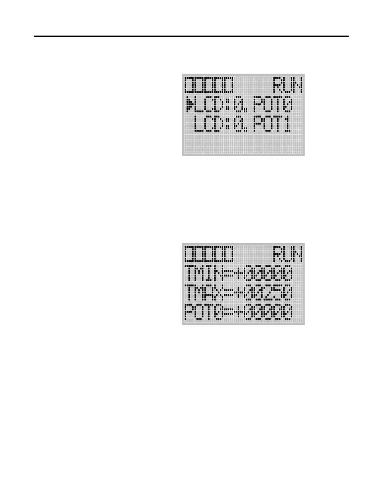
2. Then, press the OK key on the LCD keypad. The Trim Pot Select
screen is displayed, as shown below.
The last trim pot whose data value you changed is selected by default. If
you are accessing to this screen for the first time, POT0 is selected by
default.
3. Select a trim pot, either POT0 or POT1, whose data value you want to
change using the Up and Down keys on the LCD keypad. In this
example, we will select POT0.
4. Then, press the OK key on the LCD keypad. The Trim Pot 0 screen is
displayed, as shown below.
TMIN and TMAX indicate the range of data value for the trim pots,
both POT0 and POT1. The factory default for TMIN, TMAX, and
POT0 values are 0, 250, and 0 in decimal, respectively. TMIN and
TMAX on this screen are read only, but you can change them using the
LCD Function File in your application program. The TMIN and TMAX
elements can only be changed by a program download.
For more information on how to change Trim Pot configuration
including TMIN and TMAX, refer to the LCD Function File described
in the MicroLogix 1100 Programmable Controllers Instruction Set Reference
Manual, publication 1763-RM001.

 Loading...


