Rockwell Automation Publication 520-TD002A-EN-E - May 2015 25
PowerFlex 527 AC Drive Specifications
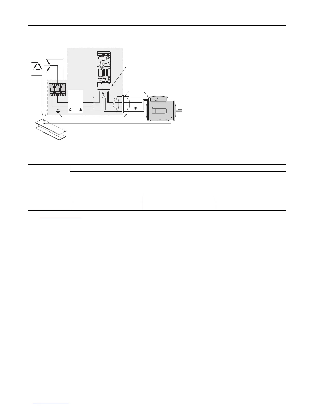
Connections and Grounding
(1) Some installations require a shielded enclosure. Keep wire length as short as possible between the enclosure entry point and the EMI filter.
(1) See Accessory Dimensions
on page 37 for more information on optional external filters.
PowerFlex 527 RF Emission Compliance and Installation Requirements
Filter Type
Standard/Limits
EN61800-3 Category C1
EN61000-6-3
CISPR11 Group 1 Class B
EN61800-3 Category C2
EN61000-6-4
CISPR11 Group 1 Class A
(Input power ≤ 20 kVA)
EN61800-3 Category C3 (I ≤ 100 A)
CISPR11 Group 1 Class A
(Input power > 20 kVA)
Internal – 10 m (33 ft) 20 m (66 ft)
External
(1)
30 m (16 ft) 100 m (328 ft) 100 m (328 ft)
R/L1
S/L2
T/L3
U/T1
V/T2
W/T3
EMI ttings and metal conduit
IP 30/NEMA 1/UL Type 1
option kit or EMC kit
Shielded enclosure
(1)
Building structure steel
Enclosure ground connection
EMI lter
L1'
L2'
L3'
L1
L2
L3
Shielded motor cable
Esc
Sel

 Loading...


