4 Rockwell Automation Publication 520-TD002A-EN-E - May 2015
PowerFlex 527 AC Drive Specifications
Common DC Bus Installations
Common DC Bus offers additional inherent breaking capabilities by utilizing all the drives/loads on the bus for energy
absorption offering higher efficiency and cost savings. The PowerFlex 527 drive has been optimized for use in Common
DC Bus or Shared DC Bus installations.
• Direct DC Bus connection to power terminal blocks.
Improved Ride Through
Operation Down to 1/2 Line Voltage
The PowerFlex 527 drive allows for the selection of 1/2 DC Bus operation, for use in critical applications where continued
drive output is desired even in the event of brown out or low voltage conditions. The PowerFlex 527 drive also supports
enhanced inertia ride through for additional low voltage mitigation.
• Selectable 1/2 line voltage operation.
• Increased power loss ride through.
Basic Position Control
Closed loop position control using Logix motion instructions such as MAM (Motion Axis Move). For more information
on Logix motion instructions, see the Logix5000 Motion Controllers Instructions Reference Manual, publication
MOTION-RM002
.
Closed Loop Feedback
Encoder Option Card
The PowerFlex 527 drive allows for configurable closed loop control with an optional encoder card for either speed or
position feedback for improved speed regulation or basic position control.
• Improved speed regulation
• Basic position control
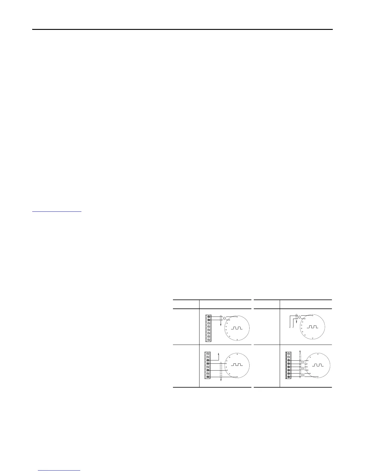
Feedback Details
Line Driver Type Incremental Encoder Option Card
• Quadrature (dual channel)
• 5V/12V DC supply, 10 mA min per channel
• Single Ended or Differential (A, B, and Z
Channel)
• Duty Cycle of 50%, +10%
• Input Frequency up to 250 kHz
I/O Connection Example I/O Connection Example
Encoder
Power –
Internal Drive
Power
Internal (drive)
12V DC, 250 mA
Encoder
Power –
External
Power
Source
Encoder
Signal –
Single-Ended,
Dual Channel
Encoder
Signal –
Differential,
Dual Channel
Common
+12V DC
(250 mA)
A
A-
B
B-
Z
Z-
Cm
+V
to SHLD
+
Common
External
Power
Supply
to
SHLD
Marker Z
A
B
Marker
Z NOT
to SHLD
to Power Supply
Common
A
A-
B
B-
Z
Z-
Cm
+V
to SHLD
A NOT
B
A
B NOT
Marker
Z NOT
Marker Z
A
A-
B
B-
Z
Z-
Cm
+V

 Loading...


